
Stabilizer bushing for vehicle and method of producing the same

Active Publication Date: 2012-11-29
SUMITOMO RIKO CO LTD
View PDF1 Cites 9 Cited by
  • Summary
  • Abstract
  • Description
  • Claims
  • Application Information

AI Technical Summary

Benefits of technology

[0011]In view of the circumstances above, the present invention provides a stabilizer bushing for a vehicle that effectively ensures superior operation stability and good riding comfort even in the case where the stabilizer bushing is inclinedly attached to a vehicle body. Furthermore, the present invention provides a method that can advantageously produce the stabilizer bushing for a vehicle.

Problems solved by technology

However, according to a research conducted by the inventors of the present invention, it is found that it is difficult to adequately ensure operation stability and good riding comfort when a conventional stabilizer bushing having two partition members embedded in a bushing body is attached to a vehicle body in an inclined state with respect to the vehicle body.

Method used


Image

  • Stabilizer bushing for vehicle and method of producing the same
  • Stabilizer bushing for vehicle and method of producing the same
  • Stabilizer bushing for vehicle and method of producing the same

Examples


Embodiment Construction

[0048]The particulars shown herein are by way of example and for purposes of illustrative discussion of the embodiments of the present invention only and are presented in the cause of providing what is believed to be the most useful and readily understood description of the principles and conceptual aspects of the present invention. In this regard, no attempt is made to show structural details of the present invention in more detail than is necessary for the fundamental understanding of the present invention, the description is taken with the drawings making apparent to those skilled in the art how the forms of the present invention may be embodied in practice.

[0049]In the following, in order to further specifically clarify the present invention, a configuration of the present invention is explained in detail with reference to the drawings.

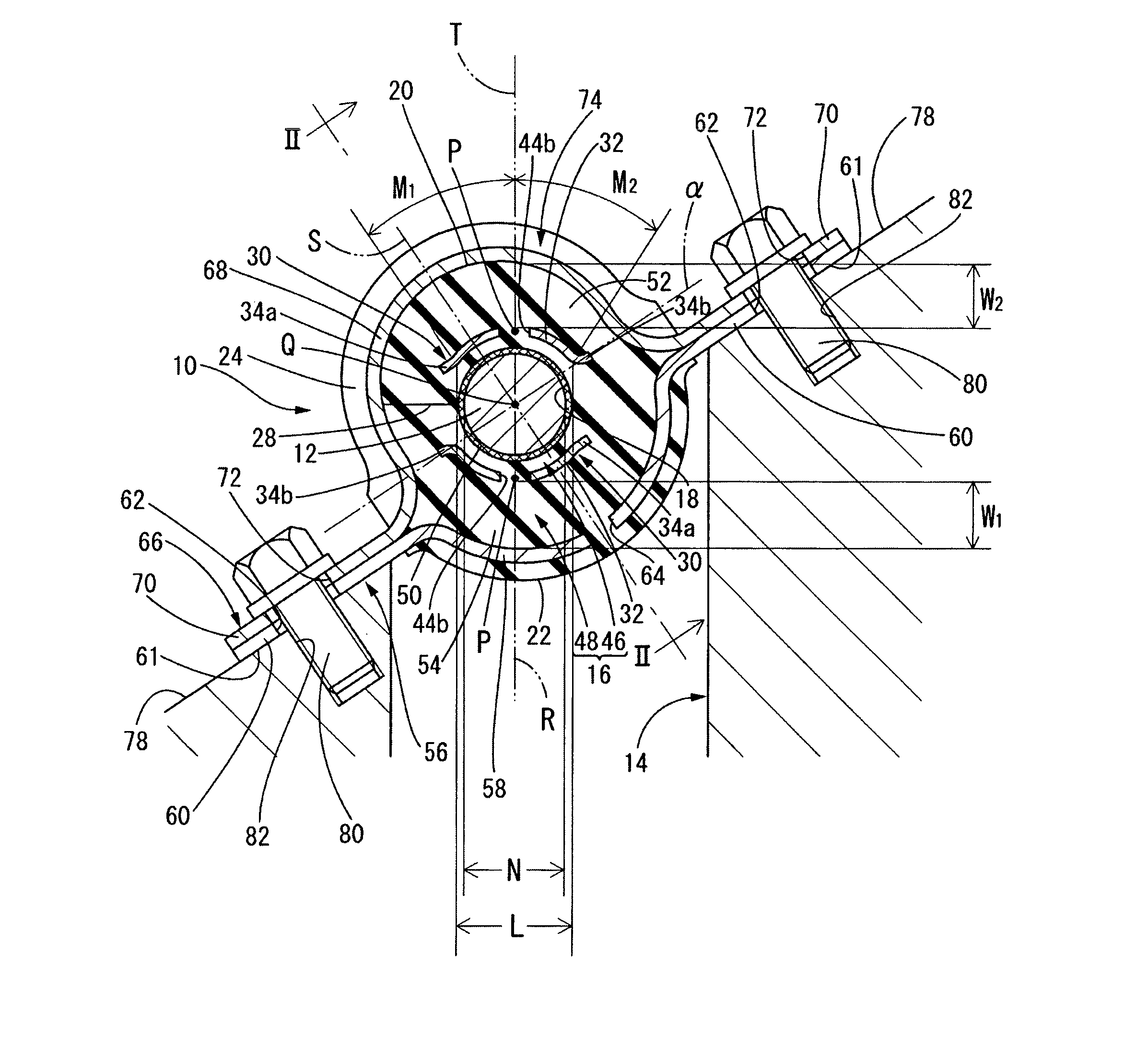
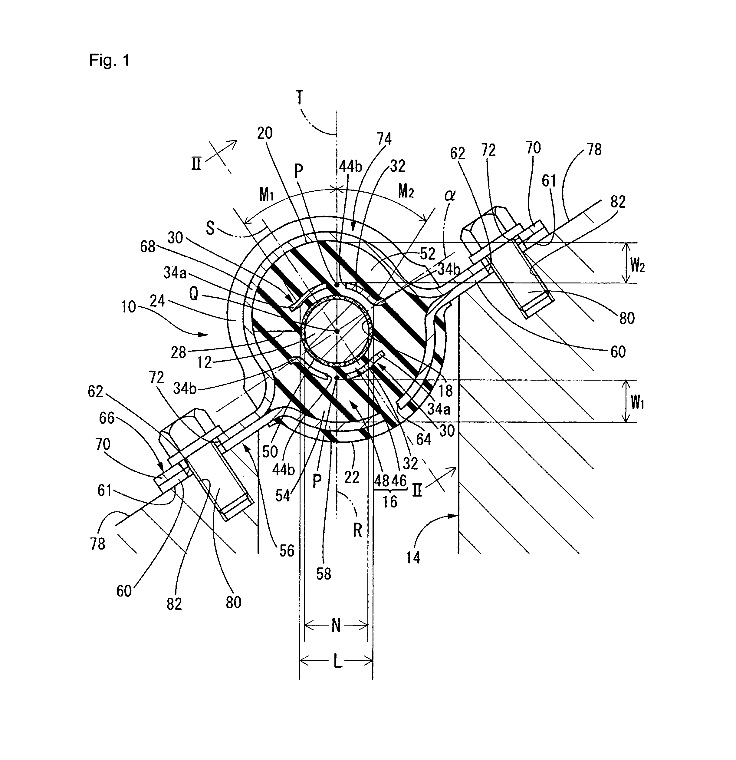
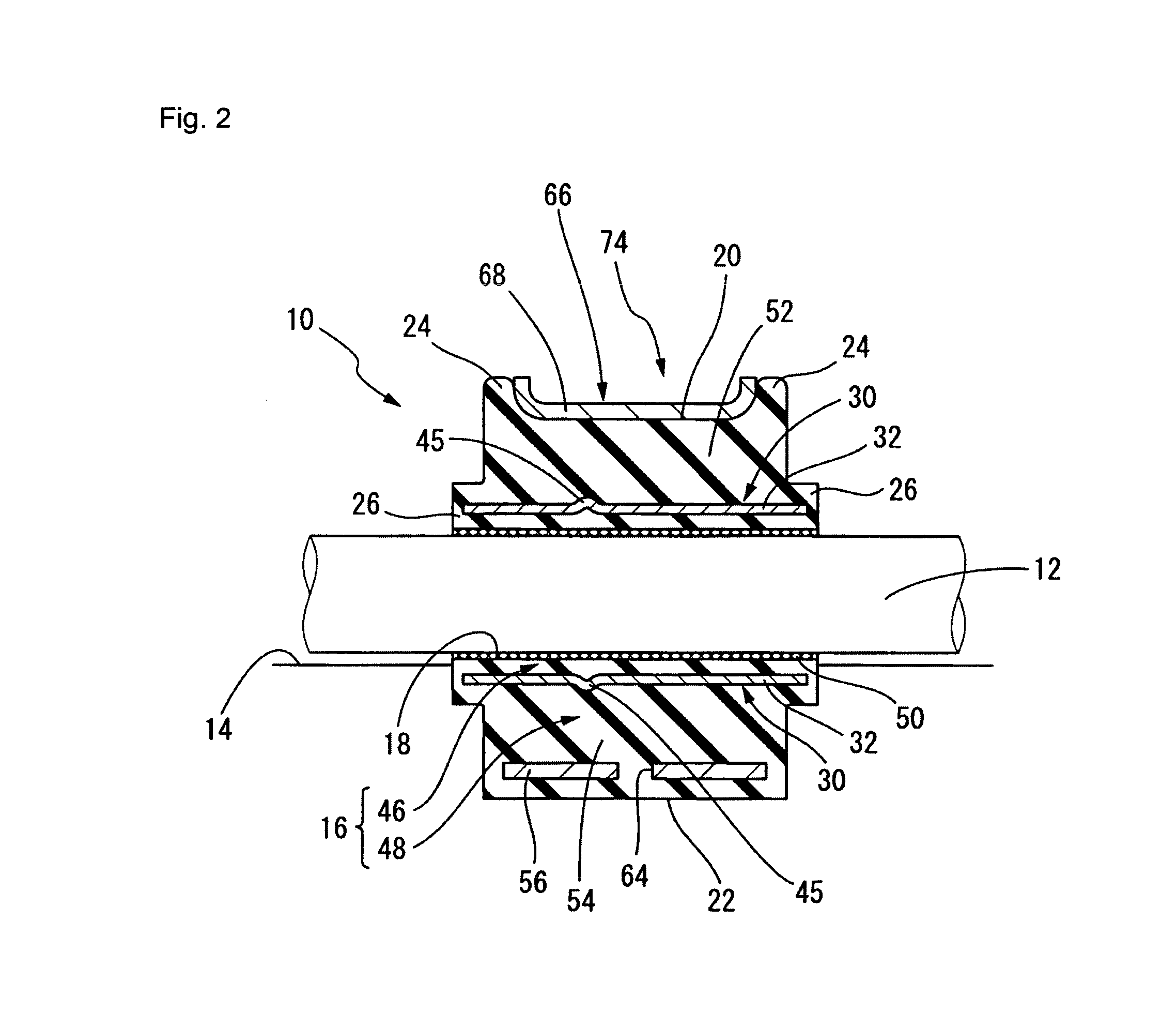
[0050]First, FIGS. 1 and 2 respectively illustrate a cross sectional form taken along a direction perpendicular to an axial direction and a cross...


PUM

PropertyMeasurementUnit
Fractionaaaaaaaaaa
Lengthaaaaaaaaaa
Thicknessaaaaaaaaaa

Abstract

Semi-tubular portions of two partition members partitioning a bushing body into an outer rubber portion and an inner rubber portion are asymmetrically arranged with respect to a reference plane containing a central axis of the bushing body and parallel to two attachment surfaces of a bracket. In addition, each of the semi-tubular portions is configured to have a length equal to or larger than a diameter of a stabilizer bar, the length being from one end to the other end in a circumferential direction of the semi-tubular portion in a projection view obtained by projecting the semi-tubular portion to a horizontal surface in a vertical direction.

Description

CROSS-REFERENCE TO RELATED APPLICATIONS[0001]The present application claims priority under 35 U.S.C. §119 of Japanese Application No. 2011-114339, filed on May 23, 2011, the disclosure of which is expressly incorporated by reference herein in its entirety.BACKGROUND OF THE INVENTION[0002]1. Field of the Invention[0003]The present invention relates to a stabilizer bushing for a vehicle and a method for producing the stabilizer bushing. More particularly, the present invention relates to a stabilizer bushing for a vehicle that is inclinedly attached to a vehicle body to support a stabilizer bar on the vehicle body in a vibration damping fashion and an advantageous method for producing such a stabilizer bushing for a vehicle.[0004]2. Description of Related Art[0005]As is well known, a stabilizer bar is mounted on a vehicle such as an automobile for the purpose of suppressing tilting of a vehicle body that occurs when the vehicle makes a turn or the like. Generally, the stabilizer bar i...

Claims


Application Information

Patent Timeline
IPC IPC(8): B60G21/055B21D53/00
CPCF16F1/16F16F1/3821B60G2204/41B60G2204/43B60G2206/427Y10T29/49668B60G2206/8106B60G2206/8207B60G21/0551B60G2204/1222B60G2206/80
Inventor NAGAI, HIROAKIYANAGINO, HIDEOKOBAYASHI, KOUICHIHOMMA, YUJI
Owner SUMITOMO RIKO CO LTD
Learn More