Vehicle seat

a seat and vehicle technology, applied in the field of seat, can solve the problems of foreign body feeling to the seated person

Inactive Publication Date: 2012-11-29
TOYOTA BOSHOKU KK
View PDF4 Cites 22 Cited by
  • Summary
  • Abstract
  • Description
  • Claims
  • Application Information

AI Technical Summary

Benefits of technology

[0006]The present invention has been made in view of the above circumstances, and an object of the present invention is to provide a vehicle seat capable of wiring a wire harness on a stretched net without causing a foreign-body feeling to a seated person.
[0007]According to an illustrative embodiment of the present invention, there is provided a vehicle seat comprising: a pad support which includes a net for supporting a cushion pad; and a wire harness which is wired while being hung on the net via a clip attached to the net in a state of not causing a foreign-body feeling to a seated person.
[0010]According to this configuration, since the clip is attached to the extra length part of the net, it is possible to securely prevent the foreign-body feeling from being caused to the seated person.

Problems solved by technology

However, as the thickness of the cushion pad 520 is made thinner, there is a problem that the S-shaped springs 534 cause a foreign-body feeling to the seated person.
However, in this technique, another problem occurs that an attachment member for hanging the wire harness W on the stretched net causes a foreign-body feeling to the seated person when the wire harness W is wired in the stretched net.

Method used


Image

  • Vehicle seat
  • Vehicle seat
  • Vehicle seat

Examples


embodiment 1

Illustrative Embodiment 1

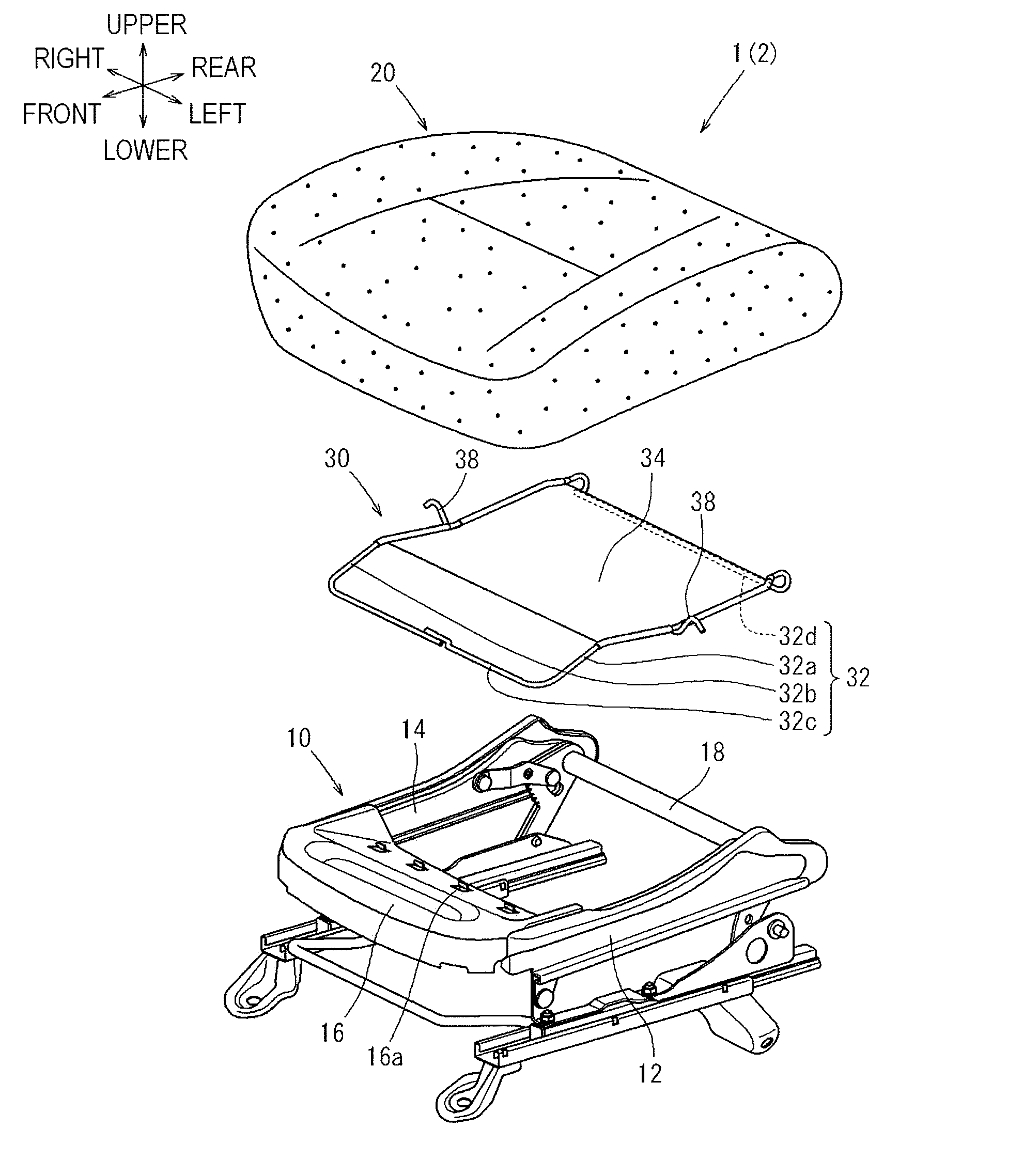
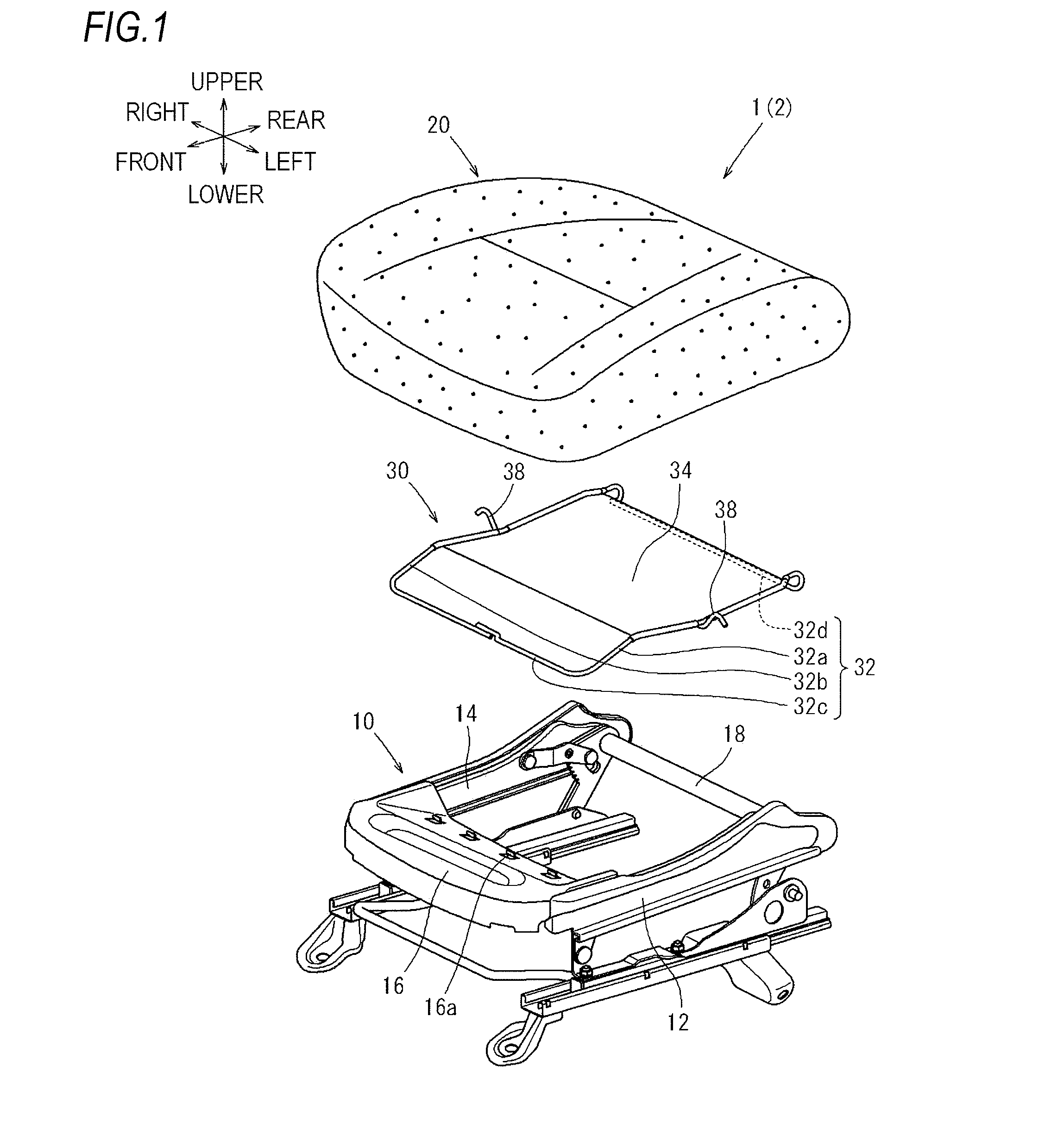
[0023]First, an illustrative embodiment 1 of the present invention will be described by referring to FIGS. 1 to 3. In the following description, a front seat 1 (for example, a driver's seat or a passenger seat) will be described as an example of a vehicle seat. Further, in the following description, upper, lower, front, rear, left and right directions respectively correspond to upper, lower, front, rear, left and right directions shown in the accompanying drawings, and refer to the upper, lower, front, rear, left and right directions on a basis of the front seat 1. This is similarly applied to all illustrative embodiments described later.

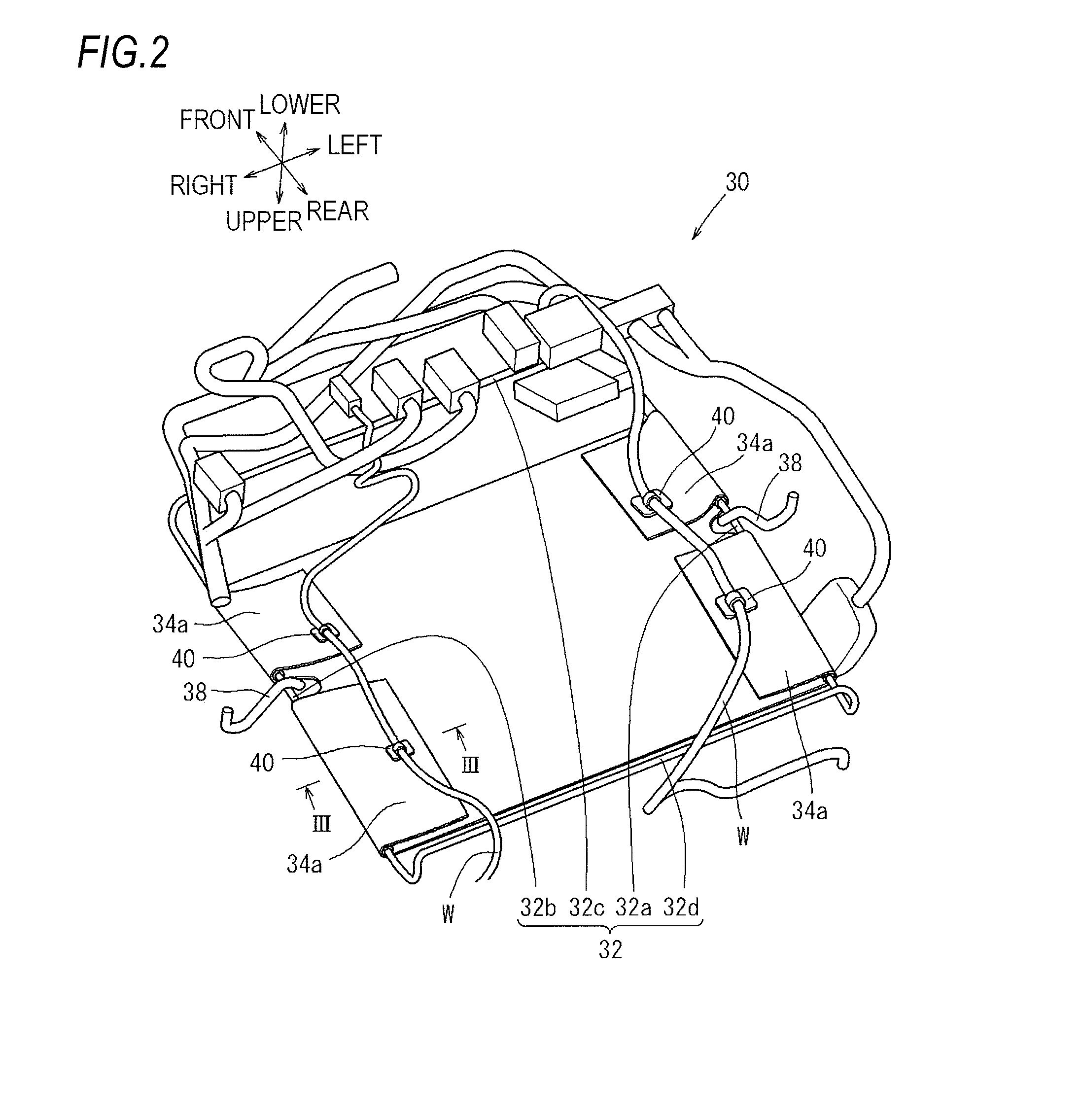
[0024]First, an overall configuration of the front seat 1 according to the illustrative embodiment 1 of the present invention will be described by referring to FIGS. 1 and 2. The front seat 1 mainly includes a seat cushion 2 and a seat back (not shown). Hereinafter, a detailed configuration of the seat cushion 2 will be desc...

embodiment 2

Illustrative Embodiment 2

[0037]Next, an illustrative embodiment 2 of the present invention will be described by referring to FIG. 4. The front seat 101 of the illustrative embodiment 2 is improved in an appearance of the extra length part 34a of the net 34 in a state where the wire harness W is wired, as compared to the front seat 1 of the illustrative embodiment 1 described above. Meanwhile, in the following description, the same or similar element will be denoted by the same reference numeral as that of the illustrative embodiment 1, and the duplicated explanation thereof will be omitted. This is similarly applied to all illustrative embodiments described below.

[0038]Hook and loop fasteners (Velcro tapes: registered trademark) 134c are respectively sewn in an end of each extra length part 34a of the net 34 and each inner surface of the net 34 opposed to the end.

[0039]The front seat 101 according to the illustrative embodiment 2 of the present invention is configured as mentioned a...

embodiment 3

Illustrative Embodiment 3

[0040]Next, an illustrative embodiment 3 of the present invention will be described by referring to FIG. 5. In the front seat 201 of the illustrative embodiment 3, the wire harness W is firmly hung on the net 34, as compared to the front seat 1 of the illustrative embodiment 1 described above.

[0041]J-shaped clips 240 are respectively sewn in an end (tip end) of each extra length part 34a of the net 34. Similar to the clip 40 described in the illustrative embodiment 1, a wire harness W is inserted into (hung on) each of the clips 240.

[0042]The front seat 201 according to the illustrative embodiment 3 of the present invention is configured as described above. According to the configurations, the front seat 201 can achieve same effect as the front seat 1 of the illustrative embodiment 1. Further, according to the above configuration, since each clip 240 is respectively sewn in each extra length part 34a, it is possible to securely prevent the clip 240 from bein...


PUM


Abstract

There is provided a vehicle seat which includes a pad support which includes a net for supporting a cushion pad, and a wire harness which is wired while being hung on the net via a clip attached to the net in a state of not causing a foreign-body feeling to a seated person.

Description

BACKGROUND OF THE INVENTION[0001]1. Field of the Invention[0002]The present invention relates to a vehicle seat. More specifically, the present invention relates to a vehicle seat including a pad support having a net for supporting a cushion pad and a wire harness wired therein.[0003]2. Description of the Related Art[0004]Conventionally, there has been known a front seat 501 which includes a pad support 530 for preventing a cushion pad 520 of a seat cushion 502 from being sunk down. For example, JP-A-2010-125121 suggests, as shown in FIGS. 8 and 9, a front seat in which the pad support 530 is configured by a plurality of S-shaped springs 534. Thereby, the wire harness W can be hung on the S-shaped springs 534 via a resin attachment member 540 and thus the wire harness W can be wired in the seat cushion 502 without causing a foreign-body feeling to a seated person.[0005]In the technique like suggested in JP-A-2010-125121, for example, in order to reduce weight of the seat and secure ...

Claims


Application Information

Patent Timeline
Patent Type & Authority Applications(United States)
IPC IPC(8): B60N2/50B60N2/90
CPCB60N2/70B60N2002/0264B60N2/7094B60N2/0264
Inventor ABE, HIDEYUKI
Owner TOYOTA BOSHOKU KK
Why Eureka
Try Eureka