Cavity filter having feedback arrangement

a feedback arrangement and filter technology, applied in the field of cavity filter, can solve the problems of unstable transmission signal at stop-band frequency, difficult to effectively remove noise, and important full bandwidth utilization, and achieve the effect of improving signal quality and enhancing signal transmission stability

Inactive Publication Date: 2012-11-29
UNIVERSAL MICROWAVE TECH INC
View PDF1 Cites 8 Cited by
  • Summary
  • Abstract
  • Description
  • Claims
  • Application Information

AI Technical Summary

Benefits of technology

[0007]The present invention has been accomplished under the circumstances in view. It is one object of the present invention to provide a cavity filter, which has resonance chambers arranged at two sides between an antenna port and two signal input / output ports to perform cross coupling feedback, improving signal quality and enhancing signal transmission stability.

Problems solved by technology

However, due to limited wireless communication channels, full bandwidth utilization is quite important.
However, it is not easy to remove noises effectively and achieves excellent channel-to-channel isolation.
However, a cavity filter cannot completely isolate the stop-band energy, causing instability of transmission signal at the stop-band frequency.
According to this design, when a signal goes through the resonance chambers A01, attenuated signal components will be diffused to interfere with the performance of the cavity filter, affecting signal receiving or transmitting stability.

Method used


Image

  • Cavity filter having feedback arrangement
  • Cavity filter having feedback arrangement
  • Cavity filter having feedback arrangement

Examples


Embodiment Construction

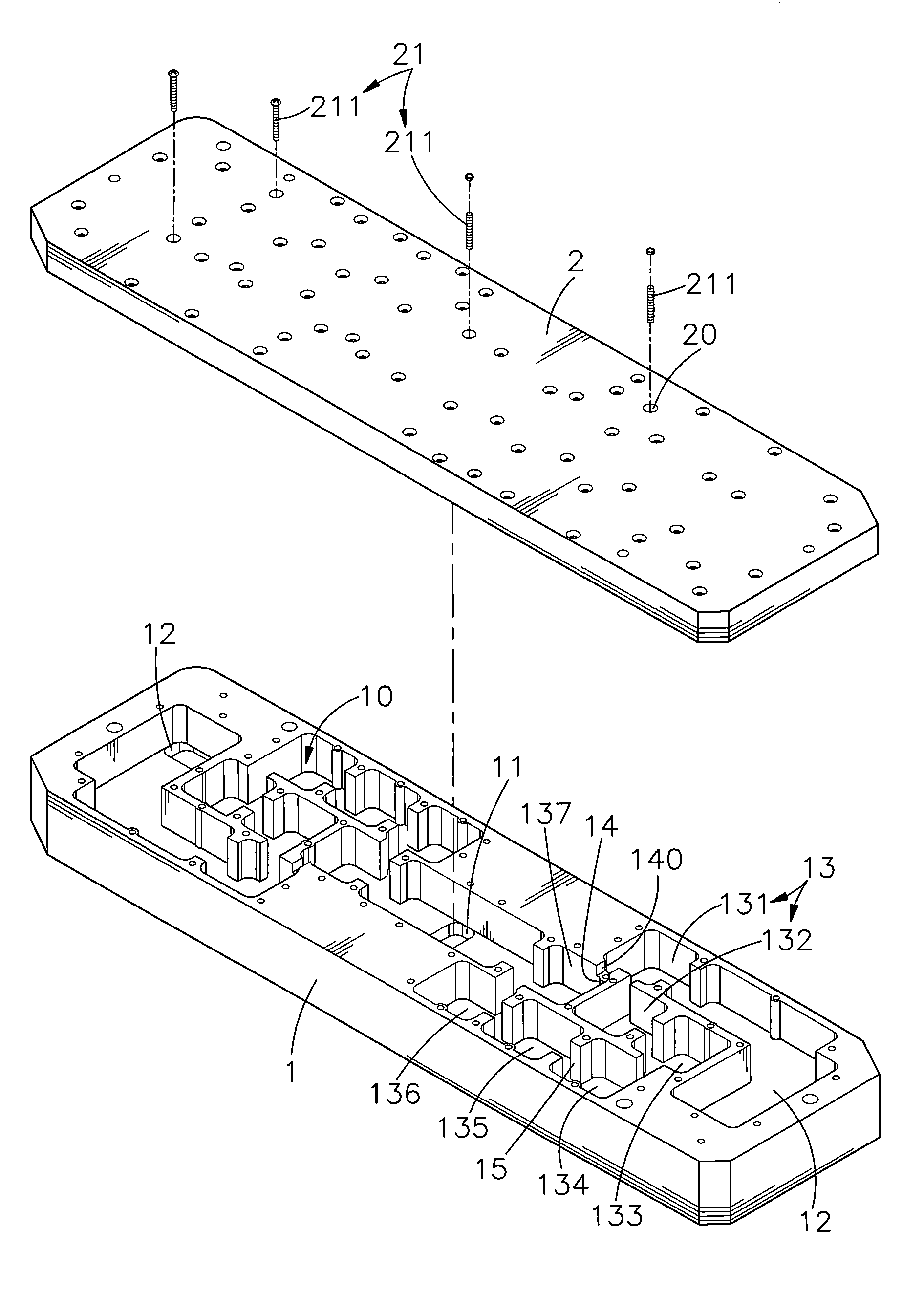
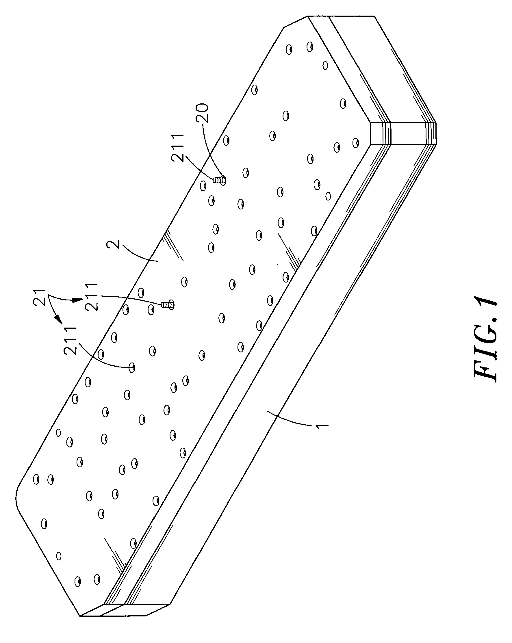
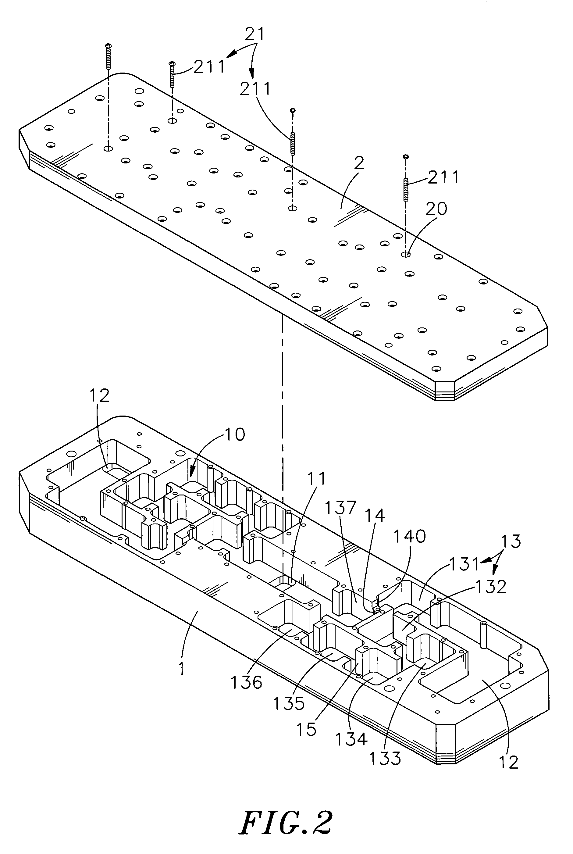
[0016]Referring to FIGS. 1-4, a cavity filter in accordance with the present invention is shown comprising a base member 1 and a cover member 2.

[0017]The base member 1 defines therein a resonant space 10, an antenna port 11 disposed at the center of the resonant space 10, two signal input / output ports 12 respectively disposed at the two distal ends of the resonant space 10 for signal input / output, two series of resonance chambers 13 respectively connected between the signal input / output ports 12 and the antenna port 11, each series of resonance chambers 13 ranging from 1st to 7th, a signal guideway 15 connected between each two adjacent resonance chambers 131˜137 of each of the two series of resonance chambers 13, an iris 14 set between the first resonance chamber 131 and last (seventh) resonance chamber 137 of each series of resonance chambers 13 and a channel 140 cut through each iris 14 in communication between the first resonance chamber 131 and last (seventh) resonance chamber ...


PUM


Abstract

A cavity filter having two series of resonance chambers bilaterally connected between an antenna port and two opposing signal input / output ports, each series of resonance chambers having the last resonance chamber thereof connected to the antenna port and the first resonance chamber thereof connected between the respective signal input / output port and the associating last resonance chamber to perform cross-coupling feedback, improving the quality of the signal received by the signal receiver using the cavity filter and enhancing signal transmission performance.

Description

BACKGROUND OF THE INVENTION[0001]1. Field of the Invention[0002]The present invention relates to electronic signal filter technology and more particularly, to a cavity filter, which has two series of resonance chambers bilaterally connected between an antenna port and two opposing signal input / output ports to perform cross-coupling feedback, improving the quality of the signal received by the signal receiver using the cavity filter and enhancing signal transmission performance.[0003]2. Description of the Related Art[0004]Following fast development of communication technology, many advanced wired and wireless signal transmitting and receiving equipment have been created and are widely used in different fields. However, due to limited wireless communication channels, full bandwidth utilization is quite important. For full bandwidth utilization, communication capacity and quality must be well improved. As different frequency channels may be close to one another, channel isolation must ...

Claims


Application Information

Patent Timeline
Patent Type & Authority Applications(United States)
IPC IPC(8): H01P1/207
CPCH01P1/2138H01P7/06H01P1/213H01P1/208
Inventor HSU, WEI-HONGLEE, CHIEN-CHIHWANG, JHIH-WEIHSU, WEI-CHIN
Owner UNIVERSAL MICROWAVE TECH INC
Why Eureka
Try Eureka