
Engine failure diagnosis system and watercraft having the same

a failure diagnosis and engine technology, applied in the field of system for diagnosing a failure, can solve the problems of time-consuming failure diagnosis, difficult failure diagnosis, and difficulty in performing failure diagnosis for engine components driven while the engine is running, so as to facilitate the failure diagnosis of engine components and improve the accuracy of diagnosis results. , the effect of quick and easy identification

Active Publication Date: 2012-11-29
YAMAHA MOTOR CO LTD
View PDF8 Cites 2 Cited by
  • Summary
  • Abstract
  • Description
  • Claims
  • Application Information

AI Technical Summary

Benefits of technology

[0015]According to a preferred embodiment of the present invention, the actuation command section outputs an actuation command for any of the engine components to be actuated in a given manner while the engine is stopped. The actuated condition detecting section detects an actuated condition of the engine component actuated based on the actuation command outputted by the actuation command section. Based on the detection result from the actuated condition detecting section, the failure diagnosis section diagnoses the presence of a failure in the engine component. This allows the engine component to be actuated in a given manner, even while the engine is stopped, thereby performing failure diagnosis of the subject engine component. In addition, the actuation command section and the failure diagnosis section preferably are provided in the control module which drives and controls the engine. This allows the failure diagnosis to be performed without connecting external equipment for diagnosis, such as a PC, to the control module. Thus, no complicated procedures are involved, but quick failure diagnosis is achieved. Thereby, the failure diagnosis of the engine components, which are driven while the engine is operating, is performed simply even at the time when the engine is stopped, allowing for quick and easy identification of a component that has failed and a location where a failure has occurred.
[0016]Based on the one actuation command, the actuation command section preferably actuates the plural engine components simultaneously. Thus, the failure diagnosis is immediately completed, independent of the number of the engine components to be diagnosed. This further facilitates the failure diagnosis of the engine components.
[0017]Alternatively, based on the one actuation command, the actuation command section preferably actuates the plural engine components in sequence in a certain order. Therefore, implementing the failure diagnosis for the individual “engine components” improves accuracy of the diagnosis results, achieving reliable failure diagnosis of the engine components.
[0018]The actuation command section preferably selects the particular actuated condition detecting section to be actuated based on the number of times the actuation command is outputted. This allows the actuation command to be sent only to a specific engine component to realize failure diagnosis of the specific engine component. Thus, the failure diagnosis is immediately completed in such a case that a location where a failure has occurred is estimated in advance, thereby improving the convenience of users who perform failure diagnosis of engine components.
[0019]An electrical connection condition of the wire harness is preferably changed by turning ON or OFF the switch mechanism connected to the wire harness in order to allow the actuation command section to output the actuation command. Thus, the switch mechanism has a simple construction, while operation of the actuation command section is ensured.
[0020]In the watercraft according to another preferred embodiment of the present invention, the failure diagnosis of the engine components, which are driven while the engine is operating, is performed simply even at the time when the engine is stopped, thus allowing for accurate and easy identification of a failure component and a location where a failure has occurred.

Problems solved by technology

In contrast, the failure diagnosis is difficult to perform for the engine components that are driven while the engine is running, such as an injector, a fuel pump, and a valve.
Especially, the failure diagnosis is difficult to perform at the time when the engine is stopped.
However, the operating condition data can be only obtained while the engine is running, and thus this system is only usable while the engine is running.
It is thus time consuming to start failure diagnosis.
At the same time, these systems cannot be used in locations where a PC is not available for use, which imposes a constraint on the possible repair environments.

Method used


Image

  • Engine failure diagnosis system and watercraft having the same
  • Engine failure diagnosis system and watercraft having the same
  • Engine failure diagnosis system and watercraft having the same

Examples


Embodiment Construction

[0026]Preferred embodiments of the present invention will now be described with reference to the attached figures.

[0027]FIGS. 1 to 4B illustrate preferred embodiments of the present invention.

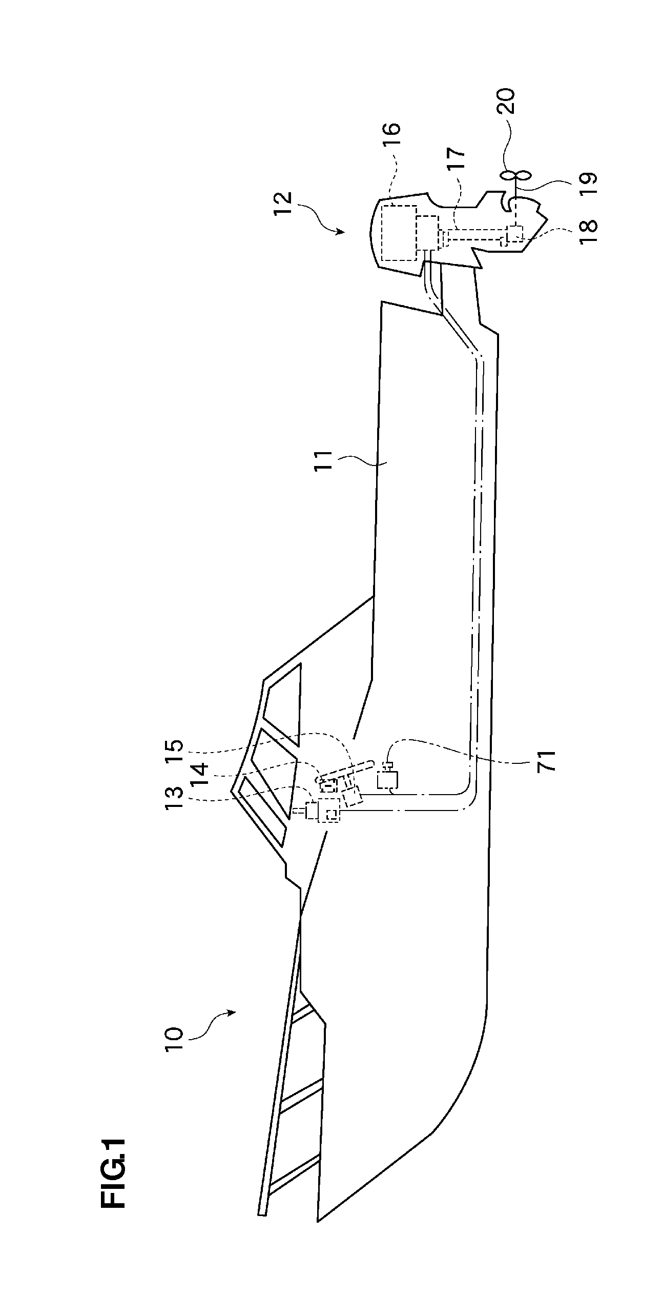
[0028]A description is first made of a construction according to a preferred embodiment of the present invention. As shown in FIG. 1, the engine failure diagnosis system according to this preferred embodiment is used for a watercraft 10 having an outboard motor 12 as a “watercraft propulsion unit” at a stern of a hull 11. The outboard motor 12 is controlled by a remote control unit 13, a key switch 14, a steering wheel unit 15, and so forth, which are located at an operator's seat of the hull 11.

[0029]As shown in FIG. 1, the outboard motor 12 has an engine 16 provided in its upper part. An output of the engine 16 is transmitted through a drive shaft 17, a shifting device 18, and a propeller shaft 19 to rotate a propeller 20.

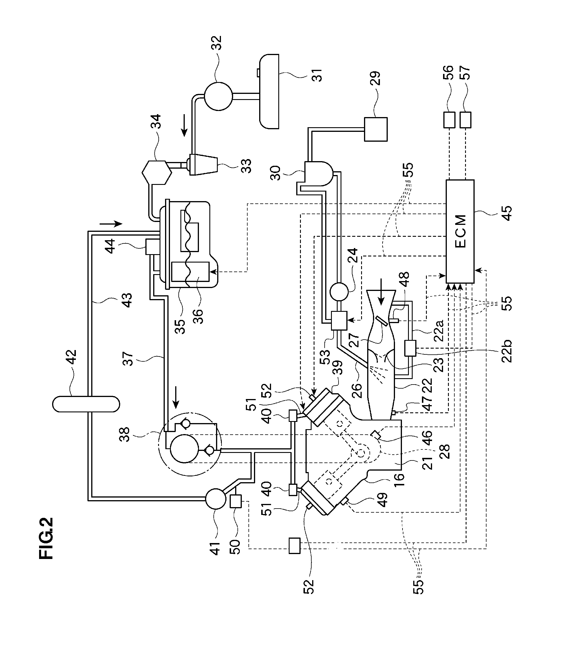
[0030]As shown in FIG. 2, the engine 16 preferably is a two-stroke, V-s...


PUM


Abstract

An engine failure diagnosis system simply performs failure diagnosis of engine components, which are driven while an engine is operating, even at the time when the engine is stopped, and identifies a component that has failed and a location where a failure has occurred. The engine failure diagnosis system includes an ECM arranged to control an engine provided in an outboard motor of a watercraft. The ECM includes an actuation command section arranged to actuate engine components, which are driven while the engine is running, in a given manner, and a failure diagnosis section arranged to diagnose the presence of a failure in the engine components. The engine components of the engine are provided with actuated condition detecting sections arranged to detect a predetermined actuated condition. When the actuation command section outputs an actuation command while the engine is stopped, the engine components are actuated in a given manner.

Description

BACKGROUND OF THE INVENTION[0001]1. Field of the Invention[0002]The present invention relates to a system for diagnosing a failure that occurs in an engine component.[0003]2. Description of the Related Art[0004]A conventional type of such engine failure diagnosis system is disclosed in JP-Y-Hei 5-11331 and JP-A-2001-193542. More specifically, in JP-Y-Hei 5-11331, an engine failure diagnosis system is activated by inserting a spare fuse into a terminal to energize circuits for sensors and electric components of the engine. The engine failure diagnosis system is designed to diagnose a failure that has occurred in the sensors or electric components, and indicates the diagnosis result by turning an alarm lamp ON.[0005]In JP-A-2001-193542, an engine failure diagnosis system is designed to use a PC. The PC is connected to an engine control unit (ECU). Sensors provide the ECU with operating condition data concerning engine components which are driven while the engine is running. The engine...

Claims


Application Information

Patent Timeline
Patent Type & Authority Applications(United States)
IPC IPC(8): G01M17/00
CPCG01M15/05
Inventor FUJINO, KENICHI
Owner YAMAHA MOTOR CO LTD
Learn More