Oscillating Positive Expiratory Pressure Device

a positive expiratory pressure and oscillating technology, applied in the direction of inhalators, life-saving devices, gymnastic exercise, etc., can solve the problems of affecting the bronchial obstruction, splitting open obstructed airways, and insufficient single cough to clear obstructions

Active Publication Date: 2012-12-06
TRUDELL MEDICAL INT INC
View PDF5 Cites 78 Cited by
  • Summary
  • Abstract
  • Description
  • Claims
  • Application Information

AI Technical Summary

Benefits of technology

[0022]In another aspect, a method of performing OPEP therapy includes receiving a flow of exhaled air along an exhalation flow path defined between an inlet and an outlet of a respiratory treatment device, accelerating the flow of exhaled air though an orifice positioned along the exhalation flow path, and reciprocating a vane adjacent the orifice between a first position and a second position in response to the flow of exhaled air throug

Problems solved by technology

However, for individuals suffering from more significant bronchial obstructions, such as collapsed airways, a single cough may be insufficient to clear the obstructions.
It is believed that OPEP therapy, or the oscillation of e

Method used


Image

  • Oscillating Positive Expiratory Pressure Device
  • Oscillating Positive Expiratory Pressure Device
  • Oscillating Positive Expiratory Pressure Device

Examples


first embodiment

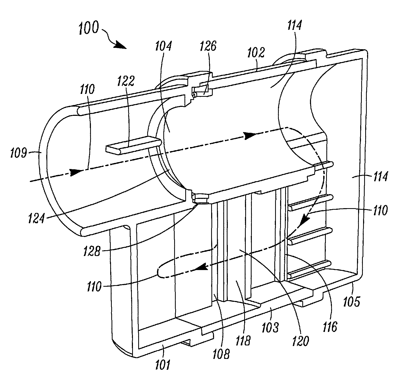
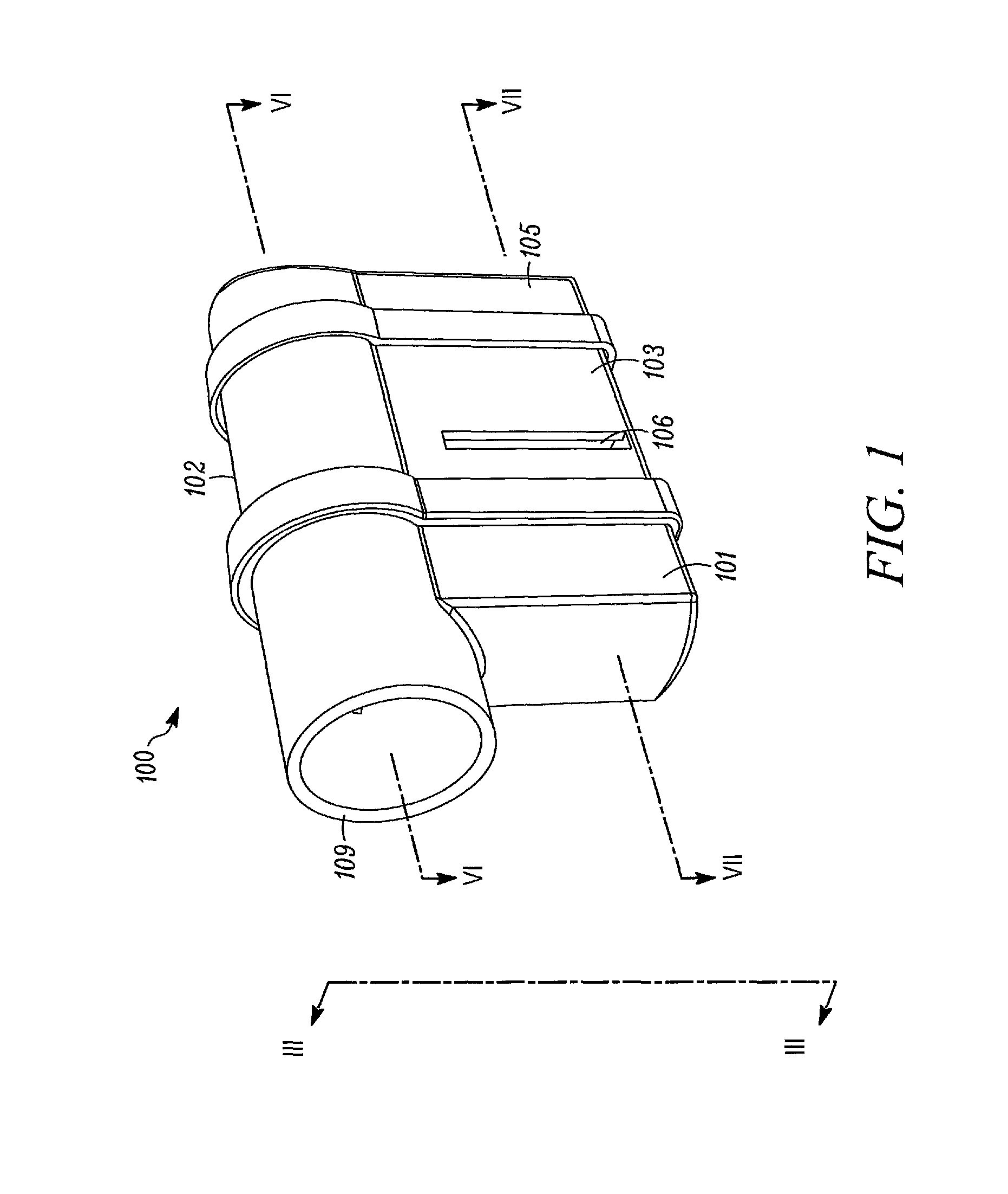
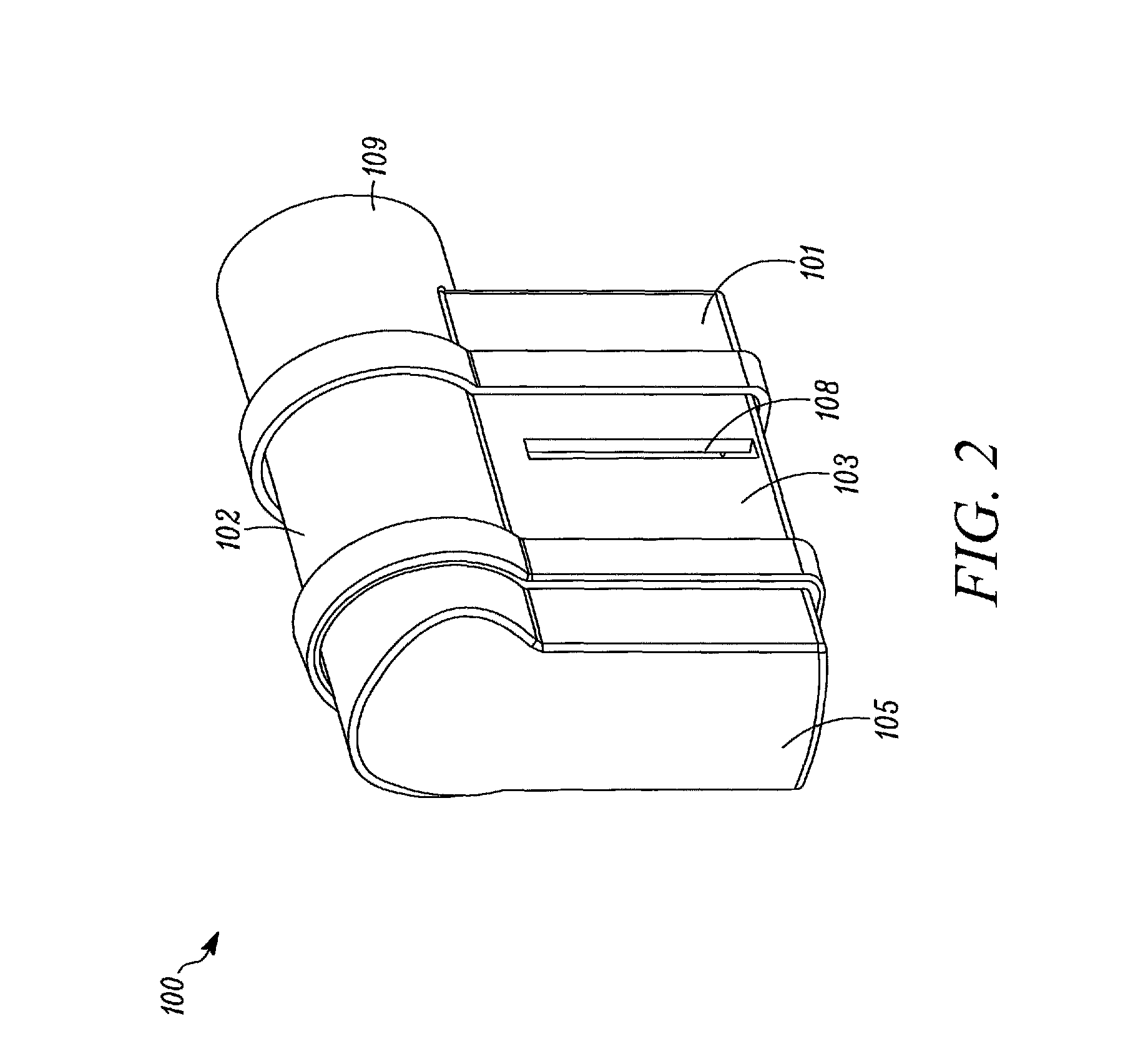
[0106]Referring first to FIGS. 1-4, a front perspective view, a rear perspective view, a cross-sectional front perspective view, and an exploded view of an OPEP device 100 are shown. For purposes of illustration, the internal components of the OPEP device 100 are omitted in FIG. 3. The OPEP device 100 generally comprises a housing 102, a chamber inlet 104, a first chamber outlet 106, a second chamber outlet 108 (best seen in FIGS. 2 and 7), and a mouthpiece 109 in fluid communication with the chamber inlet 104. While the mouthpiece 109 is shown in FIGS. 1-4 as being integrally formed with the housing 102, it is envisioned that the mouthpiece 109 may be removable and replaceable with a mouthpiece 109 of a different size or shape, as required to maintain ideal operating conditions. In general, the housing 102 and the mouthpiece 109 may be constructed of any durable material, such as a polymer. One such material is Polypropylene. Alternatively, acrylonitrile butadiene styrene (ABS) may...

second embodiment

[0133]Turning now to FIGS. 18-19, a front perspective view and a rear perspective view of a second embodiment of an OPEP device 200 is shown. The configuration and operation of the OPEP device 200 is similar to that of the OPEP device 100. However, as best shown in FIGS. 20-24, the OPEP device 200 further includes an adjustment mechanism 253 adapted to change the relative position of the chamber inlet 204 with respect to the housing 202 and the restrictor member 230, which in turn changes the range of rotation of the vane 232 operatively connected thereto. As explained below, a user is therefore able to conveniently adjust both the frequency and the amplitude of the OPEP therapy administered by the OPEP device 200 without opening the housing 202 and disassembling the components of the OPEP device 200.

[0134]The OPEP device 200 generally comprises a housing 202, a chamber inlet 204, a first chamber outlet 206 (best seen in FIGS. 23 and 32), a second chamber outlet 208 (best seen in FI...

third embodiment

[0149]Turning now to FIGS. 35-38, a third embodiment of an OPEP device 300 is shown. As described below, with the exception of an adjustment mechanism 353, the design and operation of the OPEP device 300 is the same as the OPEP device 200. For example, as seen in the front perspective view of FIG. 35, a housing 302 of the OPEP device 300 includes a mouthpiece 309, a first chamber outlet 306, and a second chamber outlet (not shown) positioned opposite the first chamber outlet 306. The housing 302 is formed of a front section 301, a middle section 303, and a rear section 305. As shown in the cross-sectional view of FIG. 36, the OPEP device 300 also includes a restrictor member 330 operatively connected to a vane 332 by a shaft (not shown), and a variable nozzle 336 separating a first chamber 314 and a second chamber 318. Finally, an exhalation flow path 310, identified by a dashed line, is formed between the mouthpiece 309 and at least one of the first chamber outlet 306 and the secon...


PUM


Abstract

A respiratory treatment device comprising at least one chamber, a chamber inlet configured to receive exhaled air into the at least one chamber, at least one chamber outlet configured to permit exhaled air to exit the at least one chamber, and an exhalation flow path defined between the chamber inlet and the at least one chamber outlet. A restrictor member positioned in the exhalation flow path is moveable between a closed position, where a flow of exhaled air along the exhalation flow path is restricted, and an open position, where the flow of exhaled air along the exhalation flow path is less restricted. A vane in fluid communication with the exhalation flow path is operatively connected to the restrictor member and is configured to reciprocate between a first position and a second position in response to the flow of exhaled air along the exhalation flow path.

Description

RELATED APPLICATIONS[0001]This application claims the benefit of U.S. Provisional Application No. 61 / 532,951, filed on Sep. 9, 2011, pending, and U.S. Provisional Application No. 61 / 493,816, filed on Jun. 6, 2011, pending, both of which are incorporated herein by reference.TECHNICAL FIELD[0002]The present disclosure relates to a respiratory treatment device, and in particular, to an oscillating positive expiratory pressure (“OPEP”) device.BACKGROUND[0003]Each day, humans may produce upwards of 30 milliliters of sputum, which is a type of bronchial secretion. Normally, an effective cough is sufficient to loosen secretions and clear them from the body's airways. However, for individuals suffering from more significant bronchial obstructions, such as collapsed airways, a single cough may be insufficient to clear the obstructions.[0004]OPEP therapy represents an effective bronchial hygiene technique for the removal of bronchial secretions in the human body and is an important aspect in ...

Claims


Application Information

Patent Timeline
IPC IPC(8): A61M16/20A61M16/14
CPCA61M15/00A61M16/208A63B23/18A61M16/0866A63B21/00196A61M16/0006A63B2071/0694A61M16/00
Inventor MEYER, ADAMENGELBRETH, DAN
Owner TRUDELL MEDICAL INT INC
Why Eureka
Try Eureka