Method for increasing subsea accumulator volume

a technology of accumulator and volume, which is applied in the direction of positive displacement liquid engine, piston pump, borehole/well accessories, etc., can solve the problems of reducing the pressure of gas and liquid, increasing the complexity of the gas, and increasing the volume of the gas, so as to achieve the effect of lowering the pressure and increasing the pressur

Active Publication Date: 2012-12-06
REEL POWER LICENSING
View PDF72 Cites 17 Cited by
  • Summary
  • Abstract
  • Description
  • Claims
  • Application Information

AI Technical Summary

Benefits of technology

[0008]The object of this invention is to provide an accumulator system which provides a relatively lower pressure at the start of the stroke of an operated device and a relatively higher pressure at the end of the stroke of an operated device.

Problems solved by technology

This is further complicated by the fact that an accumulator typically pressurizes the fluid by having compressed gas such as nitrogen provide pressure on the fluid.
A disadvantage of this is that as the liquid is discharged from the accumulator, the volume of the gas becomes larger and therefore the pressure of the gas and liquid becomes lower.

Method used


Image

  • Method for increasing subsea accumulator volume
  • Method for increasing subsea accumulator volume
  • Method for increasing subsea accumulator volume

Examples


Embodiment Construction

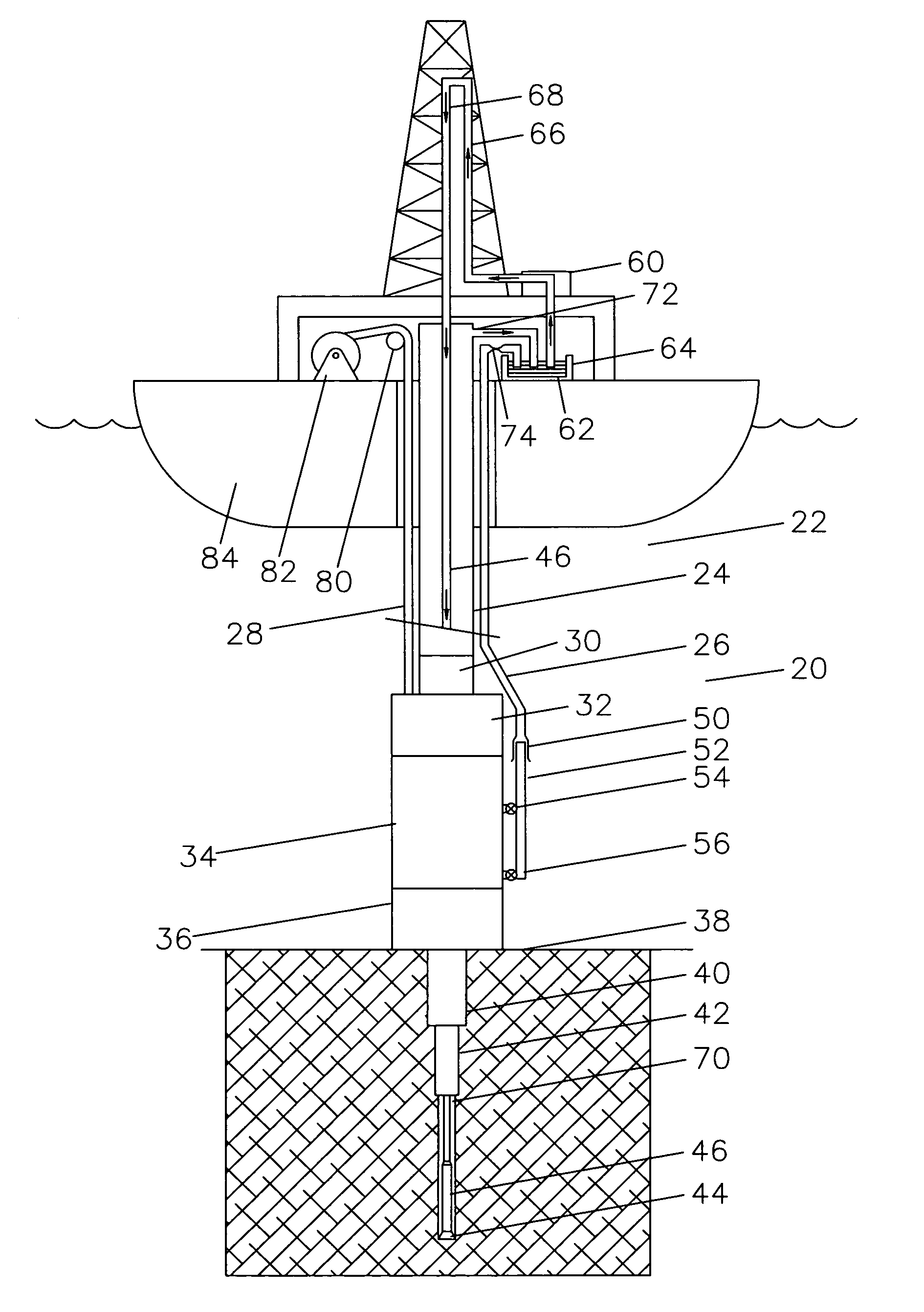
[0023]Referring now to FIG. 1, a view of a complete system for drilling subsea wells 20 is shown in order to illustrate the utility of the present invention. The drilling riser 22 is shown with a central pipe 24, outside fluid lines 26, and cables or hoses 28.

[0024]Below the drilling riser 22 is a flex joint 30, lower marine riser package 32, lower blowout preventer stack 34 and wellhead 36 landed on the seafloor 38.

[0025]Below the wellhead 36, it can be seen that a hole was drilled for a first casing string 40, that first casing string 40 was landed and cemented in place, a hole drilled through the first string for a second string, the second string 42 cemented in place, and a hole is being drilled for a third casing string by drill bit 44 on drill string 46.

[0026]The lower Blowout Preventer stack 34 generally comprises a lower hydraulic connector for connecting to the subsea wellhead system 36, usually 4 or 5 ram style Blowout Preventers, an annular preventer, and an upper mandrel...


PUM


Abstract

In a subsea system where subsea devices are operated using a pressurized fluid from one or more accumulators, the method of providing flow of pressurized fluid to operate a device which is greater than the flow from an accumulator providing the flow, comprising discharging the accumulator to drive one or more motors, driving one or more pumps by the one or more motors, the one or more pumps having a larger displacement than the one or more motors such that the one or more pump outputs a greater volume of fluid than the motor consumes, and delivering the output of the one or more pumps to operated the subsea device.

Description

TECHNICAL FIELD[0001]This invention relates to the general subject of providing for the flow of fluids in a subsea environment in which volumes are required to be stored under pressure in bottles as a ready reserve and are needed to be deployed to operate low pressure functions, high pressure functions, and functions which require low pressure at one time and high pressure at another time.CROSS-REFERENCE TO RELATED APPLICATIONS[0002]Not applicable.STATEMENT REGARDING FEDERALLY SPONSORED RESEARCH OR DEVELOPMENT[0003]Not applicableREFERENCE TO A “MICROFICHE APPENDIX”[0004]Not applicableBACKGROUND OF THE INVENTION[0005]The field of this invention is that of providing fluid power to operate subsea components such as the shear rams of subsea blowout preventers and similar components. These components typically make up what is called a subsea blowout preventer stack and have a high volume requirement to operate an appropriate number of these functions. It can range up to 200 gallons of ac...

Claims


Application Information

Patent Timeline
Patent Type & Authority Applications(United States)
IPC IPC(8): E21B43/01
CPCE21B33/064E21B43/01E21B33/063F04B9/08
Inventor BAUGH, BENTON FREDERICK
Owner REEL POWER LICENSING
Why Eureka
Try Eureka