

Antenna apparatus and communication terminal
- Summary
- Abstract
- Description
- Claims
- Application Information
AI Technical Summary
Benefits of technology
Problems solved by technology
Method used
Image

Examples
first preferred embodiment
[0027]An antenna apparatus according to the first preferred embodiment and a communication terminal including the antenna apparatus will be described with reference to FIGS. 2 to 6.
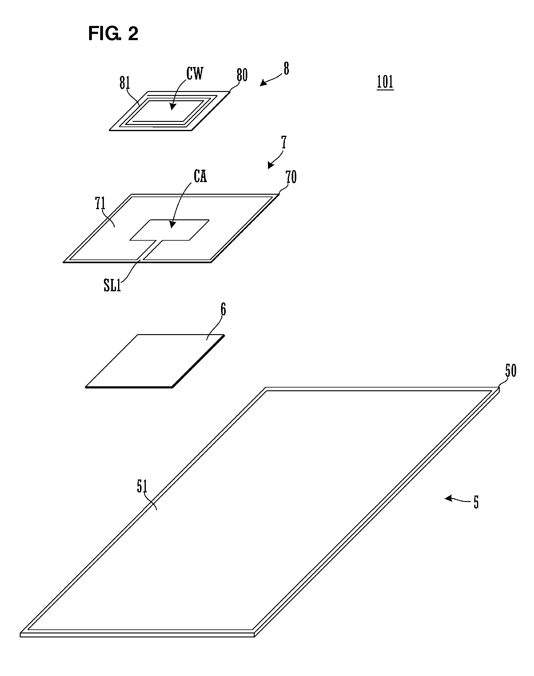
[0028]FIG. 2 is an exploded perspective view of an antenna apparatus 101 according to the first preferred embodiment. FIG. 3A is a plan view of a communication terminal including the antenna apparatus 101. FIG. 3B is an elevation view of the communication terminal.
[0029]An antenna module according to the present preferred embodiment is preferably use in NFC (Near Field Communication: short-range communication) such as Felica (registered trademark) and uses the HF band having a center frequency of 13.56 MHz, for example.
[0030]The antenna apparatus 101 illustrated in FIG. 2 includes a power supply coil 8, a booster electrode sheet 7, a magnetic sheet 6, and a ground substrate 5 arranged in this order from the top. The antenna apparatus 101 preferably is a laminate including these elements.
[0031]The power su...
second preferred embodiment
[0058]FIG. 7 is an exploded perspective view of an antenna apparatus 102 according to the second preferred embodiment.
[0059]The antenna apparatus 102 illustrated in FIG. 7 includes the power supply coil 8, the booster electrode sheet 7, the magnetic sheet 6, and the ground substrate 5 arranged in this order from the top. The antenna apparatus 102 preferably is the laminate of these elements.
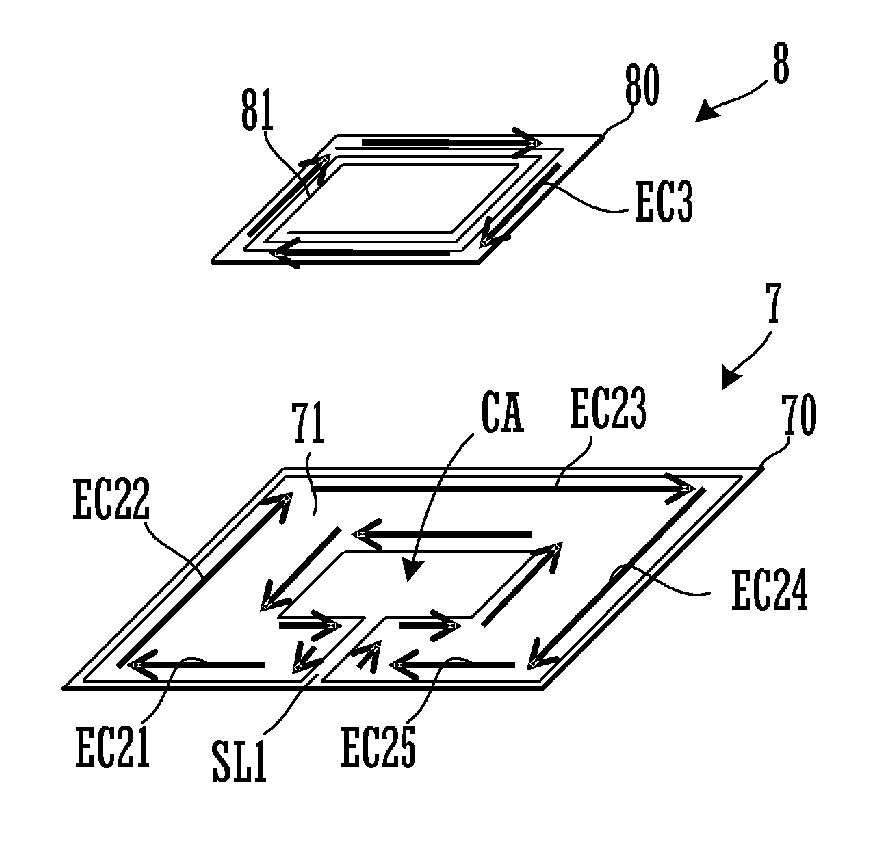
[0060]The shape of the magnetic sheet 6 is different from the shape of the magnetic sheet 6 in the antenna apparatus 101 according to the first preferred embodiment illustrated in FIG. 2. Referring to FIG. 7, a chain double-dashed line represents a position at which the magnetic sheet 6 covers the booster electrode sheet 7. The magnetic sheet 6 not only covers the conductor aperture CA and the slit portion SL1 of the booster electrode 71, but also extends to a region where the slit portion SL1 divides the periphery, that is, a region where the currents EC21 and EC25 flow.
[0061]In the case of the ...
third preferred embodiment
[0062]FIG. 8 is an exploded perspective view of an antenna apparatus 103 according to the third preferred embodiment.
[0063]The antenna apparatus 103 illustrated in FIG. 8 includes the booster electrode sheet 7, the power supply coil 8, the magnetic sheet 6, and the ground substrate 5 arranged in this order from the top. The antenna apparatus 103 preferably is the laminate of these elements.
[0064]The positional relationship between the booster electrode sheet 7 and the power supply coil 8 is different from that in the antenna apparatus 101 according to the first preferred embodiment illustrated in FIG. 2. Thus, the power supply coil 8 may be present between the booster electrode sheet 7 and the magnetic sheet 6. That is, a current flowing around the conductor aperture CA of the booster electrode 71 and a current flowing along both sides of the slit portion SL1 of the booster electrode 71 are interrupted by the magnetic sheet 6, and only a current flowing along the outer edge of the b...
PUM
 Abstract
Description
Claims
Application Information