
Nuclear magnetic flowmeter

Active Publication Date: 2014-01-30
KRONE GMBH
View PDF8 Cites 7 Cited by
  • Summary
  • Abstract
  • Description
  • Claims
  • Application Information

AI Technical Summary

Benefits of technology

The patent describes a device that can magnetize a medium by using an inner carrier and an outer carrier. The orientation between these carriers can be achieved by rotating both carriers around the same axis. The outer carrier is easier to control than the inner carrier, so the preferred method is to rotate the outer carrier. The device also includes an electromagnet that can change the strength of the magnetic field in the medium without needing to mechanically adjust the field. This makes it easier to control the magnetic properties of the medium.

Problems solved by technology

However, test separators are not able to reliably measure proportions of crude oil smaller than 5%.
Since the proportion of crude oil of each source continuously drops and the proportion of crude oil of a host of sources is already less than 5%, it is not currently possible to economically exploit these sources using test separators.
In general, deviations of the macroscopic magnetic field which is permeating the medium from the ideal of the homogeneous magnetic field lead to a reduced measurement quality and thus to inaccurate measurement results.

Method used


Image

  • Nuclear magnetic flowmeter
  • Nuclear magnetic flowmeter
  • Nuclear magnetic flowmeter

Examples


Embodiment Construction

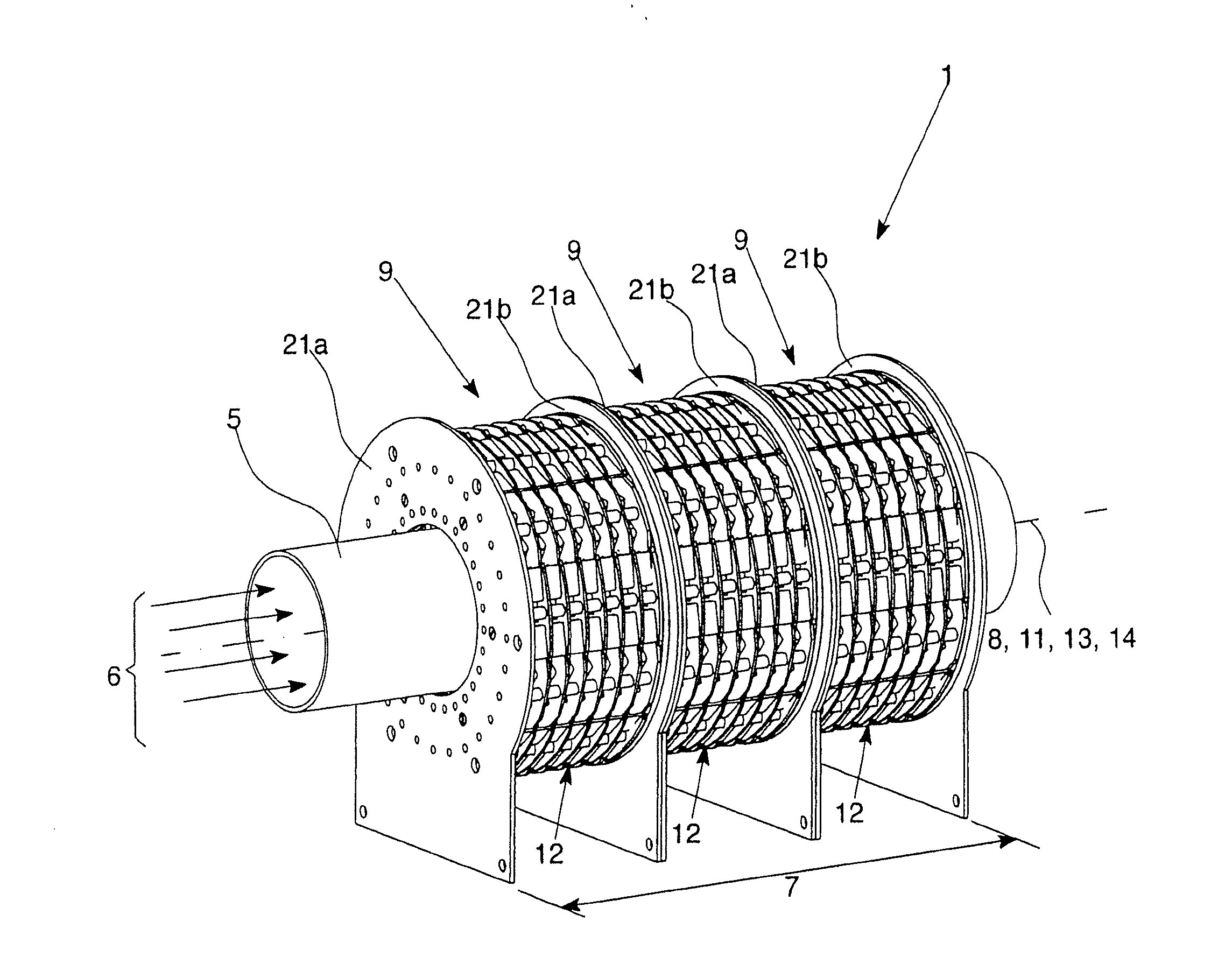
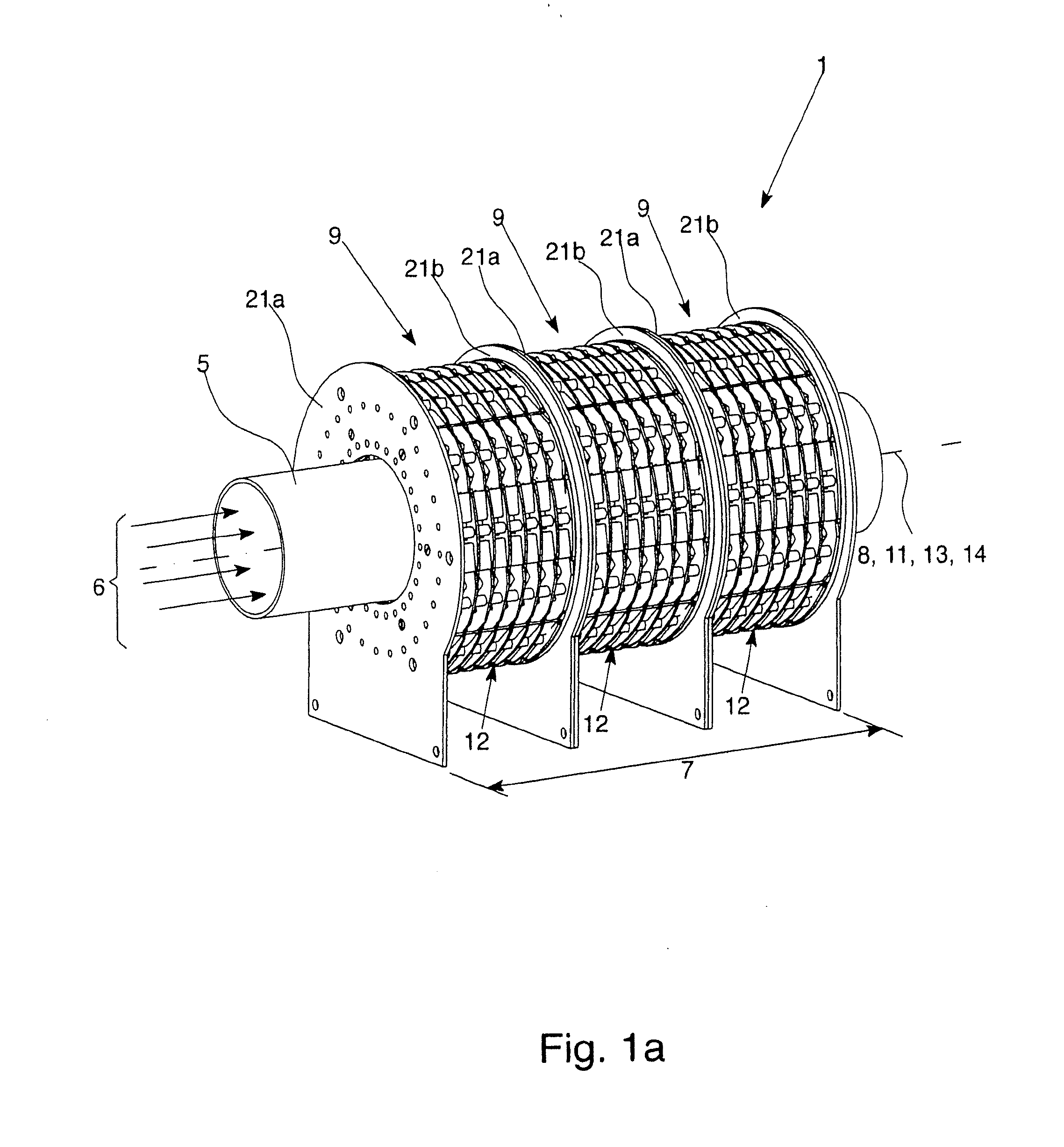
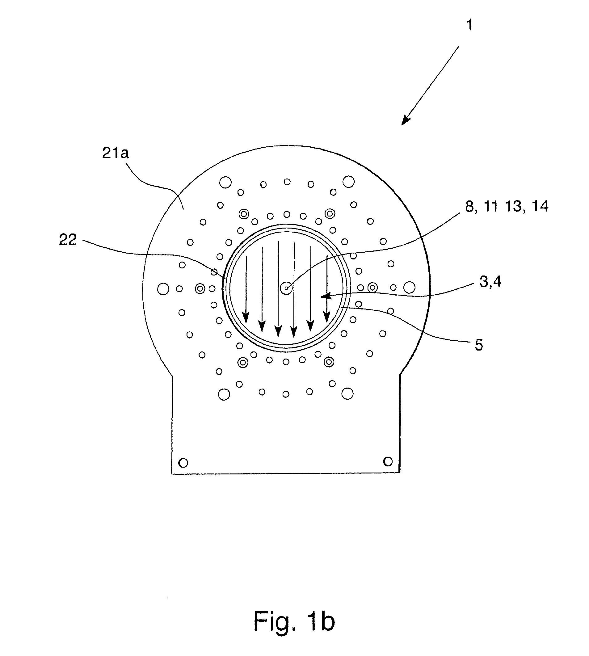
[0041]A nuclear magnetic flowmeter for measuring a medium 6 flowing through a measuring tube 5, in accordance with the invention, comprises a magnetization apparatus 1 for magnetization of the medium 6 flowing through the measuring tube 5 over a magnetization distance 7 along the longitudinal axis 8 of the measuring tube 5. Here, the magnetization apparatus 1 for producing the magnetic field 3, 4 for magnetizing the medium 6 is provided with permanent magnets 2, and the magnetization apparatus 1 has at least two magnetization segments 9 which are located in succession in the direction of the longitudinal axis 8 of the measuring tube 5 represented by the broken line in FIG. 1a and the central circle in FIG. 1b.

[0042]In accordance with the invention the magnetic field 3, 4 in the medium 6 has the same direction over the entire magnetization distance 7.

[0043]The figures show one exemplary embodiment of a magnetization apparatus 1 which belongs to the nuclear magnetic flowmeter in acco...


PUM


Abstract

A magnetization device with a magnetic field which is generated by permanent magnets for variable magnetization of a medium flowing through a tube over a magnetization distance along the longitudinal axis of the tube. The magnetization device improves the quality of the results relative to known nuclear magnetic resonance measurement and analysis methods in that the magnetic field in the medium has a single direction over the magnetization distance.

Description

BACKGROUND OF THE INVENTION[0001]1. Field of the Invention[0002]The invention relates to a nuclear magnetic flowmeter for measuring the flow rate of a medium flowing through a measuring tube, with a magnetization apparatus for magnetization of the medium flowing through the measuring tube over a magnetization distance along the longitudinal axis of the measuring tube, the magnetization apparatus for producing the magnetic field which is used to magnetize the medium being provided with permanent magnets and having at least two magnetization segments which are located in succession in the direction of the longitudinal axis of the measuring tube.[0003]2. Description of Related Art[0004]The atomic nuclei of the elements which have a nuclear spin also have a magnetic moment which is caused by the nuclear spin. The nuclear spin can be construed as an angular momentum which can be described by a vector, and accordingly, the magnetic moment can also be described by a vector which is paralle...

Claims


Application Information

Patent Timeline
IPC IPC(8): G01F1/716
CPCG01F1/716G01F1/56
Inventor ZOETEWEIJ, MARCO LEENDERTBOUSCHE, OLAF JEAN PAULHOGENDOORN, CORNELIS JOHANNESDE GRAAF, ARIELPORS, JAN TEUNIS AARTRAMONDT, JAN-WILLEM
Owner KRONE GMBH
Learn More