Magnetic head to prevent undesired data erasure and magnetic disk storage having the same

a magnetic head and data technology, applied in the direction of magnetic recording heads, data recording, instruments, etc., can solve the problems of difficult to increase the density of areal cells, and achieve the effects of reducing the field applied, reducing the leakage field, and weakening the magnetic flux concentration

Inactive Publication Date: 2009-06-02
WESTERN DIGITAL TECH INC
View PDF19 Cites 1 Cited by
  • Summary
  • Abstract
  • Description
  • Claims
  • Application Information

AI Technical Summary

Benefits of technology

[0011]Therefore, the present invention has a feature to provide a magnetic head in which no data erasure occurs even when a stray field is applied in parallel to the medium surface of an HDD and thereby provide a high density magnetic disk storage.
[0013]According to the present invention, the head structure has a function to weaken magnetic flux concentration on the edges of the auxiliary pole, lower shield and upper shield and reduce the leakage field from the edges of the auxiliary pole, lower shield and upper shield, and reduce the field applied to the magnetic recording layer. Here, the “head air-bearing surface” means a surface of a magnetic layer which faces the medium, where the magnetic layer is a component of the magnetic head except a protective film of non-magnetic material such as carbon.
[0014]According to the present invention, when a stray field is applied to the HDD, particularly in parallel to the medium of the HDD, leakage field from the auxiliary pole, lower shield and upper shield can be reduced and a write head which does not cause write bit degradation and erasure in the magnetic recording layer and an HDD incorporating the same can be provided.

Problems solved by technology

However, the current longitudinal recording method has a problem that as the write bit length decreases, it becomes difficult to increase the areal density due to thermal fluctuation in medium magnetization.

Method used


Image

  • Magnetic head to prevent undesired data erasure and magnetic disk storage having the same
  • Magnetic head to prevent undesired data erasure and magnetic disk storage having the same
  • Magnetic head to prevent undesired data erasure and magnetic disk storage having the same

Examples


Embodiment Construction

[0032]Next, specific embodiments of the present invention will be described referring to the accompanying drawings. To facilitate understanding, elements with like functions are designated by like reference numerals.

[0033]FIG. 7 is a conceptual diagram showing a magnetic disk storage according to an embodiment of the present invention. In this magnetic disk storage, a magnetic head mounted on a slider 13 fixed to the tip of a suspension arm 12 writes and reads magnetization signals at a given position on a magnetic disk (magnetic recording medium) 11 which is rotated by a motor 28. A rotary actuator 15 is driven to select a magnetic head position (track) in the magnetic disk radial direction. A write signal to the magnetic head and a read signal from it are processed by signal processing circuits 35a and 35b.

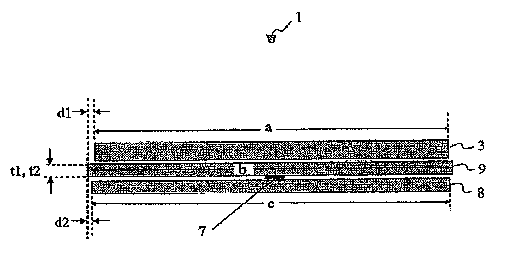
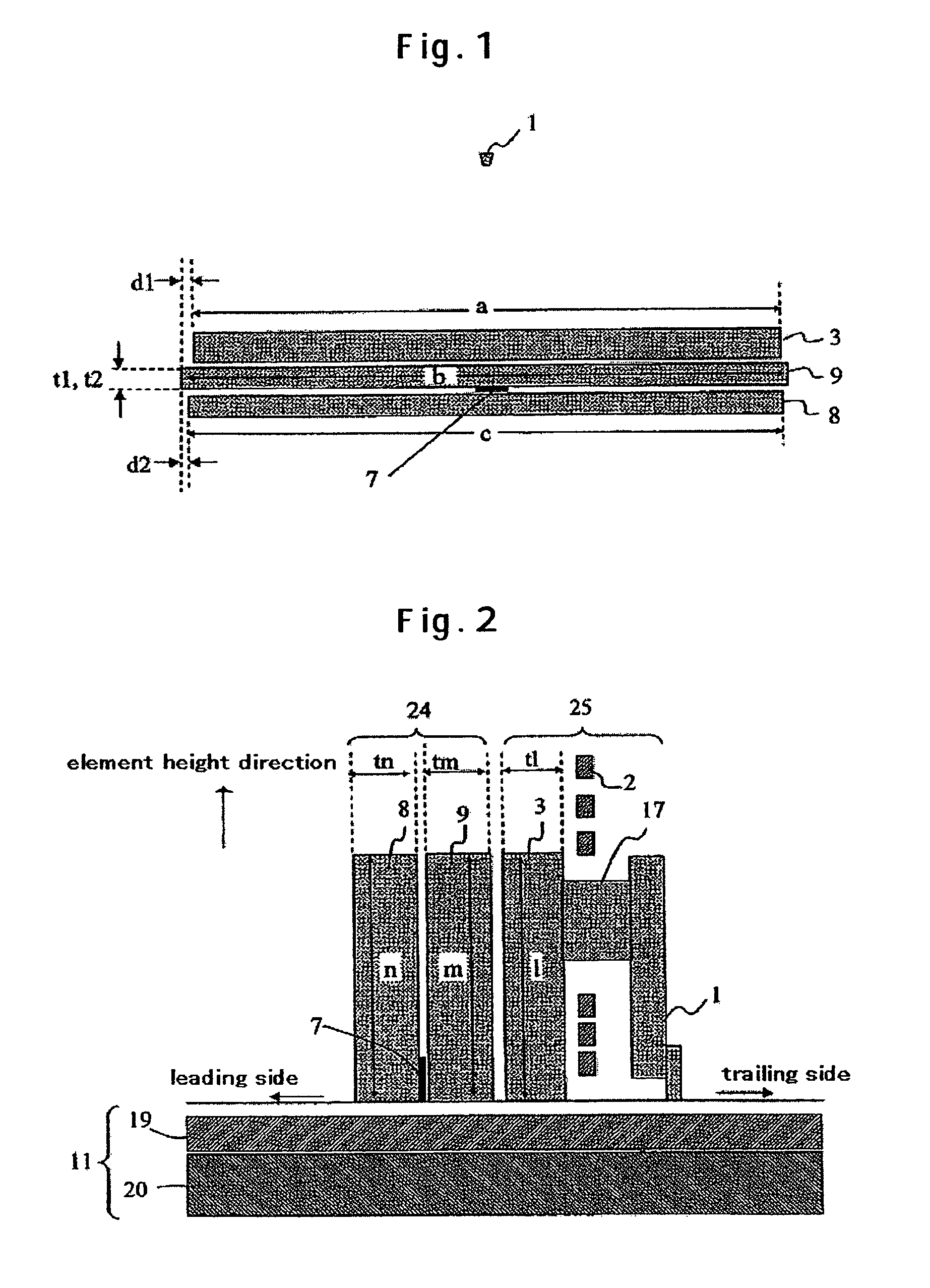
[0034]FIG. 1 is a plan view which schematically shows a head air-bearing surface in a magnetic head according to an embodiment of the present invention. FIG. 2 schematically sh...


PUM

PropertyMeasurementUnit
widthaaaaaaaaaa
thicknessaaaaaaaaaa
thicknessaaaaaaaaaa

Abstract

Embodiments of the invention provide a magnetic head (magnetic disk storage) which does not erase data on a recording medium even when a stray field is applied. In one embodiment, the head has a structure that d1<t1 and d2<t2 are satisfied where d1denotes the positional difference between edges of an auxiliary pole and an upper shield in the cross-track direction, d2 denotes the positional difference between edges of the upper shield and a lower shield in the cross-track direction, t1 the film thickness of the auxiliary pole or upper shield, whichever magnetic layer is larger in cross-track width, and t2 the film thickness of the upper shield or lower shield, whichever magnetic layer is larger in cross-track width.

Description

CROSS-REFERENCES TO RELATED APPLICATIONS[0001]This application claims priority from Japanese Patent Application No. JP 2004-301911, filed Oct. 15, 2004, the entire disclosure of which is incorporated herein by reference.BACKGROUND OF THE INVENTION[0002]The present invention relates to a perpendicular recording magnetic head and a magnetic disk storage which incorporates the same.[0003]In a magnetic disk storage, data on a recording medium is read or written by a magnetic head. In order to increase the magnetic disk's recording capacity per unit area, a higher areal density is needed. However, the current longitudinal recording method has a problem that as the write bit length decreases, it becomes difficult to increase the areal density due to thermal fluctuation in medium magnetization. A solution to this problem is a perpendicular recording method whereby magnetization signals are recorded in a direction perpendicular to the medium surface.[0004]The perpendicular recording method ...

Claims


Application Information

Patent Timeline
Patent Type & Authority Patents(United States)
IPC IPC(8): G11B5/127
CPCG11B5/1278
Inventor FUKUI, HIROSHIMARUYAMA, YOJIMOCHIZUKI, MASAFUMIOKADA, TOMOHIRO
Owner WESTERN DIGITAL TECH INC
Why Eureka
Try Eureka