Electrohydrodynamically formed structures of carbonaceous material

a technology of electrohydrodynamic and carbonaceous material, applied in the field of carbon structure, can solve the problems of increasing the susceptibility to damage during transfer and/or fitting of items, reducing flexibility and compliance, and reducing the field of effect of field

Active Publication Date: 2019-04-04
THE TRUSTEES FOR PRINCETON UNIV
View PDF3 Cites 0 Cited by
  • Summary
  • Abstract
  • Description
  • Claims
  • Application Information

AI Technical Summary

Benefits of technology

[0004]The present invention is directed to a method for depositing carbonaceous materials utilizing an electrohydrodynamic cell. In the present invention methods are provided in which carbonaceous materials in a suspension medium are deposited on electrodes by applying an electric field having a first direction, varying the intensity to drive lateral movement, building up layers, fixing the layers in place, then reducing the field and removing the electrodes. The method of claim 1, wherein at least one of the electrodes further comprises a substrate in contact with or electrical communication with the outer surface of the conductive material.
[0005]Among the many different possibilities contemplated, the method may advantageously utilize electrodes positioned either parallel or perpendicular to a base surface of the electrohydrodynamic cell. It is further contemplated that the method may also vary the spacing between the electrodes, the temperature, pH, or concentration of the suspension, or the duration or intensity of the applied field. The method may be utilized to create graded structures, or to deposit at least one carbonaceous material and at least one other material. It is further contemplated that the method may also involve reversing the field direction to allow deposition of materials having an overall charge opposite that of the carbonaceous materials, and this process of reversing the field may be repeated. It is also contemplated that one or more of the coated electrodes may be removed from the electrohydrodynamic cell and placed into a different electrohydrodynamic cell containing a suspension comprising a different carbonaceous material, and utilizing a similar process, which may be repeated if desired. It is contemplated that the method may also utilize a suspension of a non-carbonaceous material that can be deposited onto previously deposited coatings via electrophoretic or electrohydrodynamic deposition. It is also contemplated that at least one of the coated electrodes is covered by a material prior to electrohydrodynamic deposition, the material being selected so as to be impermeable to atoms, molecules, ions, oligomers, and polymers; or to have an intrinsic porosity in which the average channel diameter, accessibility, tortuosity, and length is selected to facilitate the passage of targeted agents such as atoms, molecules, ions, oligomers, and polymers. It is still further contemplated that the method may involve removing the layered structure from at least one of the electrodes, and that the electrodes may be dense or have an intrinsic porosity such that it may be completely or partially filled by the suspended materials in order to create a dense or a porous coating on the at least one of the anode or cathode. It is contemplated that the removed structure may be dried or exposed to EM radiation, and may also involve the reduction of the carbonaceous materials or intercalation of the layered structure.

Problems solved by technology

Such structures contain flaws created by removing the liquid through drying or filtration.
In addition, such structures can have a reduced flexibility and compliance, which can result in an increase in susceptibility to damage during transfer and / or fitting to the item to be covered.
However, in electrophoretic deposition the particles or sheets adhere at the point of initial contact to the substrate or previously deposited layers and remain fixed in position, which leaves defects or gaps between the particles or sheets comprising the layers that constitute the coating, membrane, or film.
A fully dense covering requires several layers, resulting in increased thickness of the coating, membrane, or film which limits its applications.

Method used


Image

  • Electrohydrodynamically formed structures of carbonaceous material
  • Electrohydrodynamically formed structures of carbonaceous material
  • Electrohydrodynamically formed structures of carbonaceous material

Examples


Embodiment Construction

[0016]The descriptions of the various embodiments of the present invention have been presented for purposes of illustration but are not intended to be exhaustive or limited to the embodiments disclosed. Many modifications and variations will be apparent to those of ordinary skill in the art without departing from the scope and spirit of the described embodiments. The terminology used herein was chosen to best explain the principles of the embodiments, the practical application or technical improvement over technologies found in the marketplace, or to enable others of ordinary skill in the art to understand the embodiments disclosed herein.

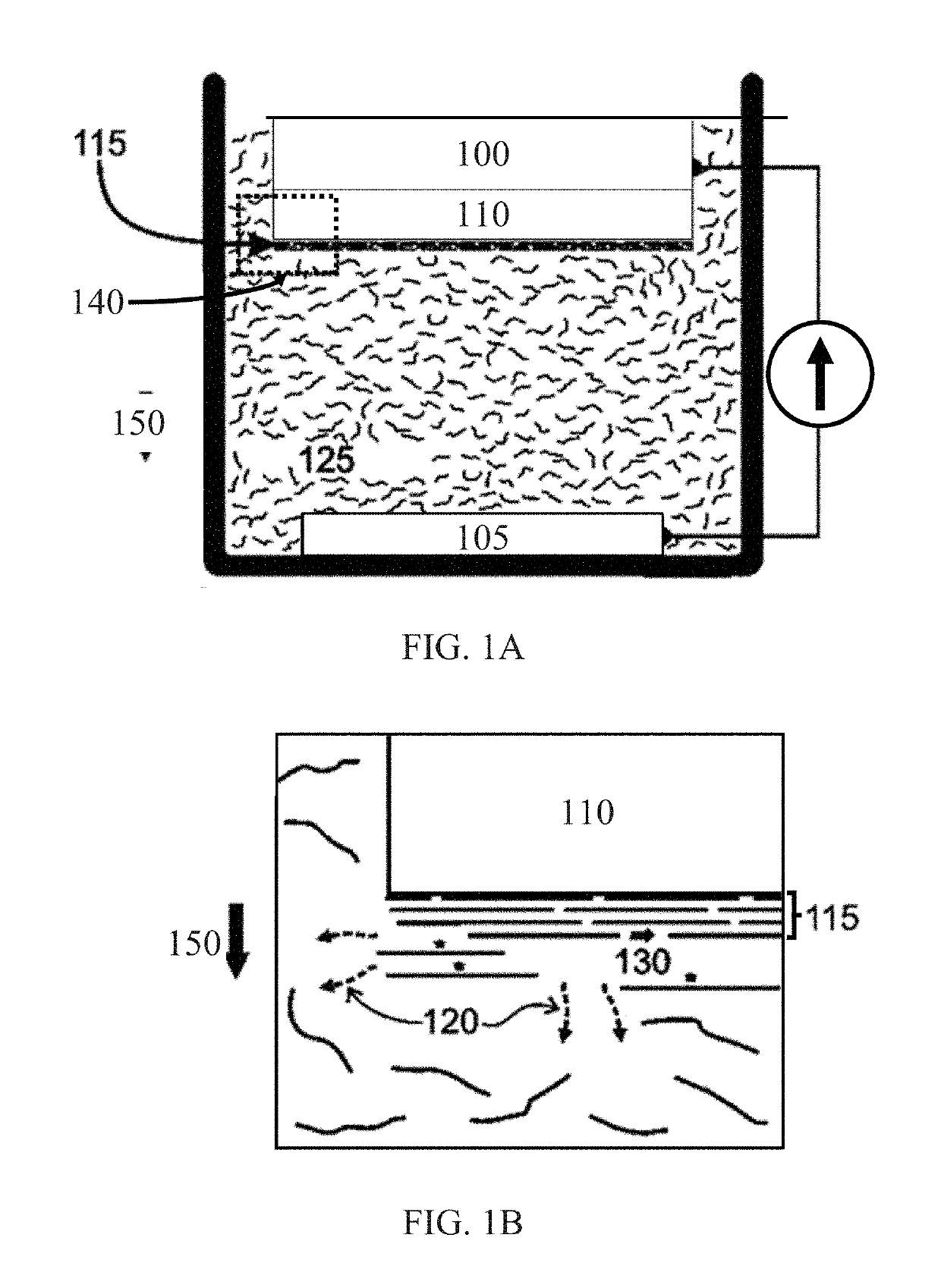
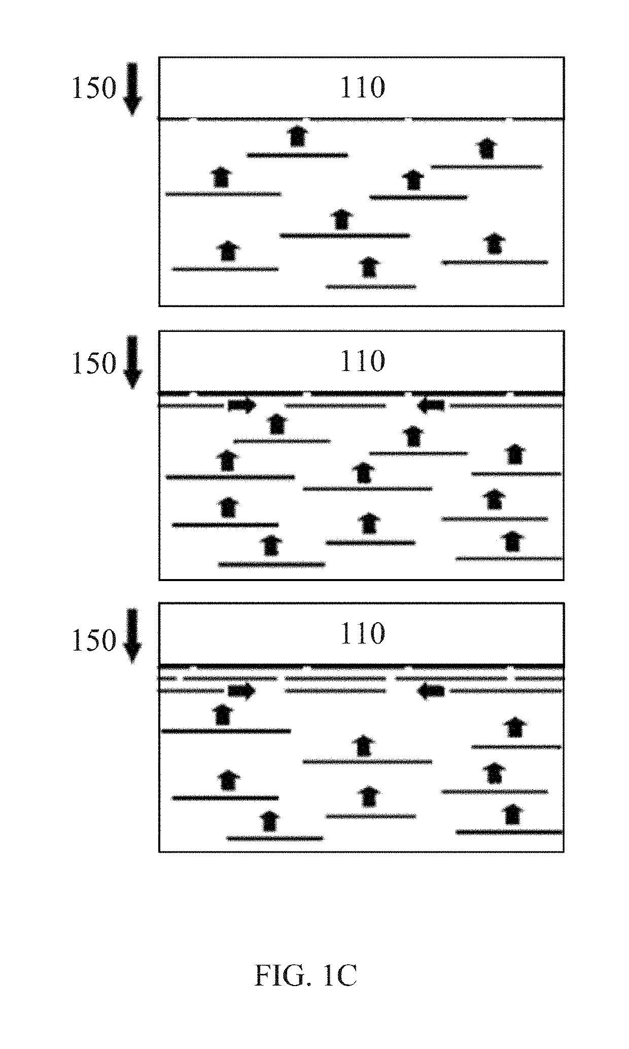
[0017]As used herein, the term “carbonaceous materials” includes any solid material, other than an inorganic carbonate, which is comprised of carbon, including mixtures or compounds comprising carbon. This includes, but is not limited to: graphite, graphite oxide, pristine graphene, graphene oxide, functionalized graphene sheets—whether those sheet...


PUM

PropertyMeasurementUnit
concentrationaaaaaaaaaa
thickaaaaaaaaaa
applied voltageaaaaaaaaaa

Abstract

A method for the electrohydrodynamic deposition of carbonaceous materials utilizing an electrohydrodynamic cell comprising two electrodes comprised of a conductive material, by first combining a solid phase comprising a carbonaceous material and a suspension medium, placing the suspension between the electrodes, applying an electric field in a first direction, varying the intensity of the electric field sufficiently to drive lateral movement, increasing the electrical field to stop the lateral transport and fix the layers in place, then removing the applied field and removing the electrodes. Among the many different possibilities contemplated, the method may advantageously utilize: varying the spacing between the electrodes; removing the buildup from one or both electrodes; placing the electrodes into different suspensions; adjusting the concentration, pH, or temperature of the suspension(s); and varying the direction, intensity or duration of the electric fields.

Description

CROSS-REFERENCE TO RELATED APPLICATIONS[0001]This application claims priority to U.S. Provisional Application No. 62 / 311,477, filed Mar. 22, 2016, which is herein incorporated by reference in its entirety.STATEMENT REGARDING FEDERALLY SPONSORED RESEARCH OR DEVELOPMENT[0002]This invention was made with government support under Grant No. DE-AR000319 awarded by the Department of Energy, Advanced Research Projects Agency-Energy (ARPA-E). The government has certain rights in the invention.BACKGROUND OF THE INVENTION[0003]The present invention relates generally to carbon structures and specifically to electrohydrodynamically formed structures of carbonaceous material. Coatings, such as physically coherent films, coatings, membranes, or tapes made from high carbon content materials, such as graphene sheets, can be assembled using electrophoretic deposition, tape casting, spin casting, drop casting, or filtration. Cast or filtered structures typically have to be at least 400 nm thick to pro...

Claims


Application Information

Patent Timeline
Patent Type & Authority Applications(United States)
IPC IPC(8): C25D13/02C25D13/22
CPCC25D13/02C25D13/22C25D7/00C01B32/192C01B32/194C01B2204/22B41J2/075B41J2/095C25D15/02
Inventor AKSAY, ILHAN A.ALAIN-RIZZO, VALERIEBOZLAR, MICHAELBOZYM, DAVID J.DABBS, DANIEL M.SZAMRETA, NICHOLASUSTUNDAG, CEM B.
Owner THE TRUSTEES FOR PRINCETON UNIV
Why Eureka
Try Eureka