Device for clamping and unclamping a tool through inductive warming of a tool holder

a tool holder and inductive heating technology, which is applied in the direction of manufacturing tools, electric/magnetic/electromagnetic heating, mechanical apparatus, etc., can solve problems such as partial weakening, and achieve the effect of reducing the field

Active Publication Date: 2012-11-13
FRANZ HAIMER MASCHINENBAU KG
View PDF14 Cites 1 Cited by
  • Summary
  • Abstract
  • Description
  • Claims
  • Application Information

AI Technical Summary

Benefits of technology

[0007]It is an object of the invention to further reduce the field on the outside of the inductive coil or on the outside of the device.
[0010]According to a further aspect of the present invention, the induction attachment is typically provided as a ring, which is closed in circumferential direction. This way, it assures an optimum shielding, since the field lines of the high frequency field are then also really captured in their entirety and they cannot escape the effect according to the invention of the induction attachment.
[0012]According to another aspect of the present invention, the induction attachment is configured so that it comprises the cross section of an overlay ring. The induction attachment thus extends from the concentrator body in radial direction beyond the concentrator and extends from the concentrator body with a slight inclination (e.g., between 10° and 20° upward) relative to horizontal, when the concentrator body is mounted as intended and aligned horizontally. This way, it forms a substantial portion of the field lines, which otherwise have the tendency to initially circumvent the concentrator body, which is a type of obstacle which is effectively flowed by these field lines. The field lines are thus used very effectively in order to generate Eddy currents and thus generating a respective opposite field in the induction attachment.
[0013]According to a further aspect of the present invention, the concentrator body can be inserted in a retaining ring on its outside. The retaining ring is used for positioning the concentrator body relative to the magnetic coil assembly. Thus, the retaining ring simultaneously also holds the induction attachment in position relative to the concentrator body, (e.g., in a position in which the concentrator body and the induction attachment are in direct surface contact with one another). Thus, a substantial amount of heat from the induction attachment can quickly flow into the concentrator body. Through such a configuration, furthermore, the handling is also simplified, since the concentrator body and the induction attachment fitting thereto are permanently connected with one another, and can be jointly replaced by a respective unit made of another concentrator body and another induction attachment fitting thereto, without the user having to consider which induction attachment has to be associated with which concentrator body. Furthermore, when the concentrator body and the induction attachment are in direct surface contact with one another, a very effective magnetic interaction between the concentrator body and the induction attachment is assured, thus a continuously shielded portion.
[0017]The retaining ring can be made of a temperature resistant plastic, which can maintain its shape at temperatures above 120° C., and up to 150° C., so that its retaining function remains assured. The production of the retaining ring from heat resistant plastic facilitates that one or plural unshrinking cycles can be performed without a break in between, and thus without the unit comprised of the induction attachment, the concentrator body and the retaining ring failing, with at least the induction attachment heating up enough, so that it thermally damages the plastic of the retaining ring. PI- or PTFE plastics are particularly suitable for the present application.
[0018]According to yet another aspect of the present invention, the plastic of the retaining ring can completely or partially reach around the induction attachment, and thus in particular also in the portion of its outer circumference, which the user would certainly touch, when attempting to lift the unit out of the induction attachment, and while attempting to lift the concentrator body and the retaining ring out of the device. This way, the risk is reduced that the user is burned directly at the heated induction attachment, since the user touches the highly heat conductive surface of the induction attachment directly.

Problems solved by technology

In this induction attachment, a magnetic field is generated, which overlays the field of the induction coil extending in the exterior of the induction coil or of the device, and thus partially weakening it.

Method used


Image

  • Device for clamping and unclamping a tool through inductive warming of a tool holder
  • Device for clamping and unclamping a tool through inductive warming of a tool holder
  • Device for clamping and unclamping a tool through inductive warming of a tool holder

Examples


Embodiment Construction

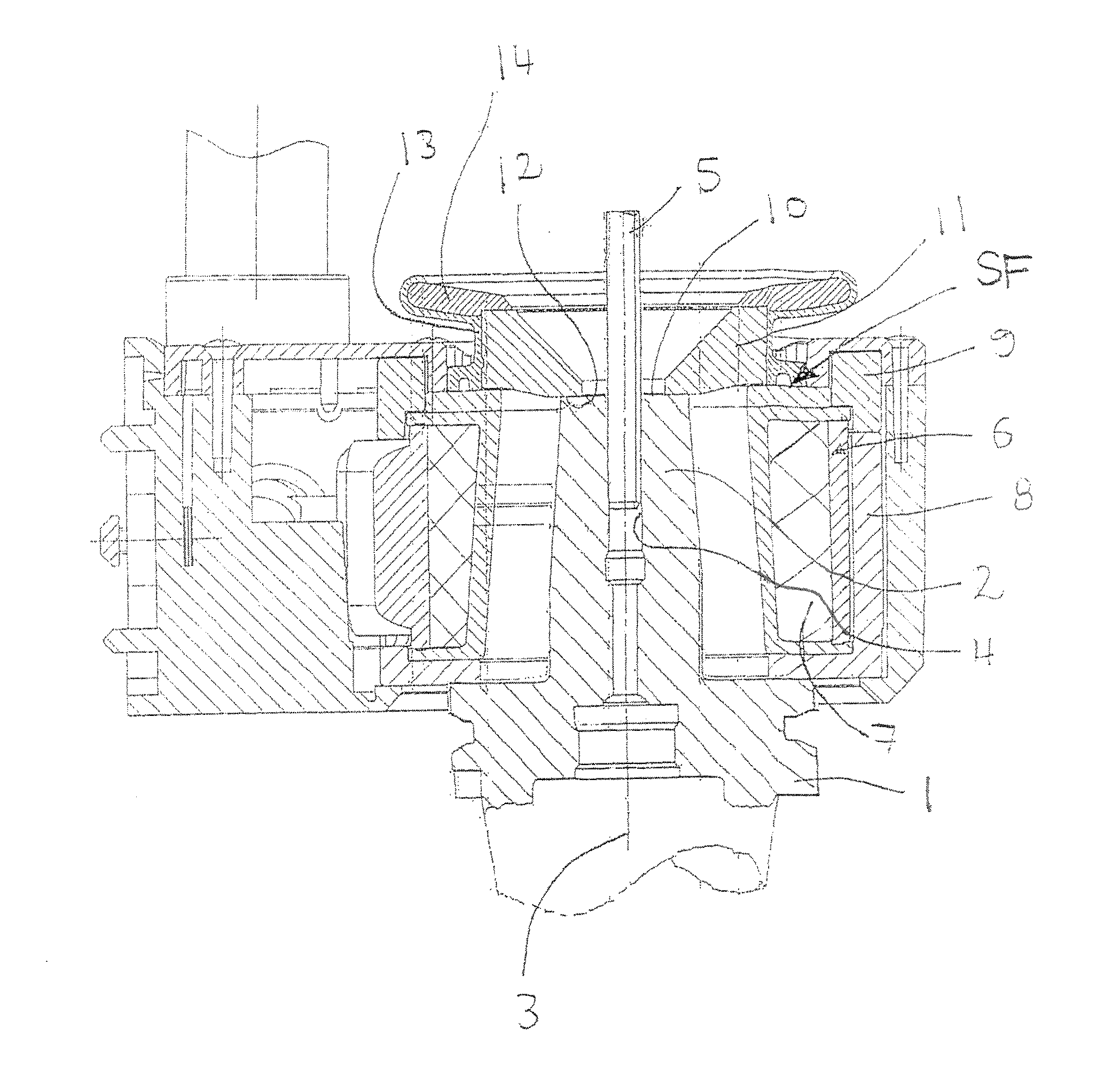
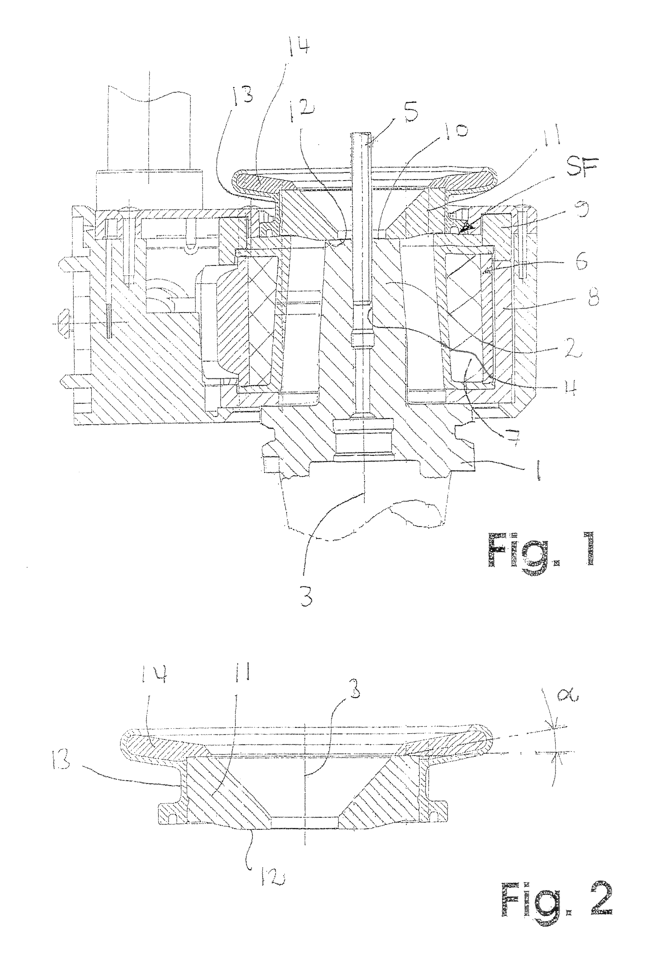
[0024]The illustrated embodiment includes a tool holder 1, which it is made of a material which is at least electrically conductive, but also magnetically conductive in this particular application, like, e.g., steel. At its other end, the tool holder comprises a sleeve section 2. The sleeve section 2 includes a receiver opening 4, centrally disposed relative to the rotation axis 3 of the tool holder, which receiver opening 4 is configured to receive a rotating tool, e.g., a drill, a cutter, or also a broaching tool, which is not shown in more detail, which can be inserted into the receiver opening 4 with its shaft 5.

[0025]The outer diameter of the shaft 5 is slightly larger than the free nominal diameter of the receiver opening 4, so that the shaft 5 is supported in the sleeve section 2 in a press fit, whereby the necessary torque can be transmitted to the rotation tool. In order to be able to insert the tool shaft 5 into the tool holder 1, or in order to be able to remove it from s...


PUM

PropertyMeasurementUnit
angleaaaaaaaaaa
temperaturesaaaaaaaaaa
temperatureaaaaaaaaaa

Abstract

A device for clamping and unclamping of tools comprising a tool shaft, by which device a sleeve section (2) of a tool holder (1) comprising a centric receiver opening (4) for a shaft (5) of a rotation tool is inductively heated, which sleeve section retains the shaft (5) of the tool seated in the receiver opening (4) in a press fit, and releases it upon heat up, which device comprises an induction coil assembly with at least one induction coil (6), which can be fed by an electric current for heating the sleeve section (2), and which comprises a concentrator body (11), which is magnetically conductive and electrically nonconductive or substantially electrically nonconductive, which concentrates the magnetic flux of the induction coil (6) onto the portion of the tool side end of the sleeve section (2), wherein the concentrator body (11) supports an induction attachment (14) made of electrically conductive material.

Description

FIELD OF THE INVENTION[0001]The invention relates to a device for inductive heating of the sleeve section of a tool holder.BACKGROUND OF THE INVENTION[0002]In particular for tools rotating at high speed, like, e.g., cutters or drills, it is known to shrink their shafts into a sleeve section of a tool holder. The sleeve section is heated for this purpose by an induction coil surrounding it, so that the tool shaft can be inserted into the receiver opening of the sleeve section, which expands or enlarges under heat influence. The outer diameter of the tool shaft is slightly larger than the nominal diameter of the receiver opening, so that the tool is held torque proof in the press fit of the tool holder after the cooling of the sleeve section.[0003]An inductive heating device suitable for this purpose is, e.g., the heating device known from DE 101 02 710 A1. This device comprises an induction coil, which can be placed over the sleeve section of the tool holder, and which thus encloses ...

Claims


Application Information

Patent Timeline
Patent Type & Authority Patents(United States)
IPC IPC(8): H05B6/10
CPCB23P11/027Y10T279/17957
Inventor HAIMER, FRANZ
Owner FRANZ HAIMER MASCHINENBAU KG
Why Eureka
Try Eureka