Electric motor

A technology for motor shafts and components, which is applied to electric components, electrical components, electromechanical devices, etc., can solve the problems of high safety and increase the weight of the motor, and achieve the effect of improving the utilization rate, improving the work efficiency and reducing the weight.

Active Publication Date: 2018-08-21
ZHUHAI PANLEI INTELLIGENT TECH CO LTD
View PDF5 Cites 5 Cited by
  • Summary
  • Abstract
  • Description
  • Claims
  • Application Information

AI Technical Summary

Problems solved by technology

However, there is a certain degree of magnetization saturation in the permanent magnet, and the volume of the permanent magnet increases with the increase of the magnetization intensity, which increases the weight of the motor; if the air gap flux density of the motor is too small, there is greater safety

Method used


Image

  • Electric motor
  • Electric motor
  • Electric motor

Examples


no. 1 example

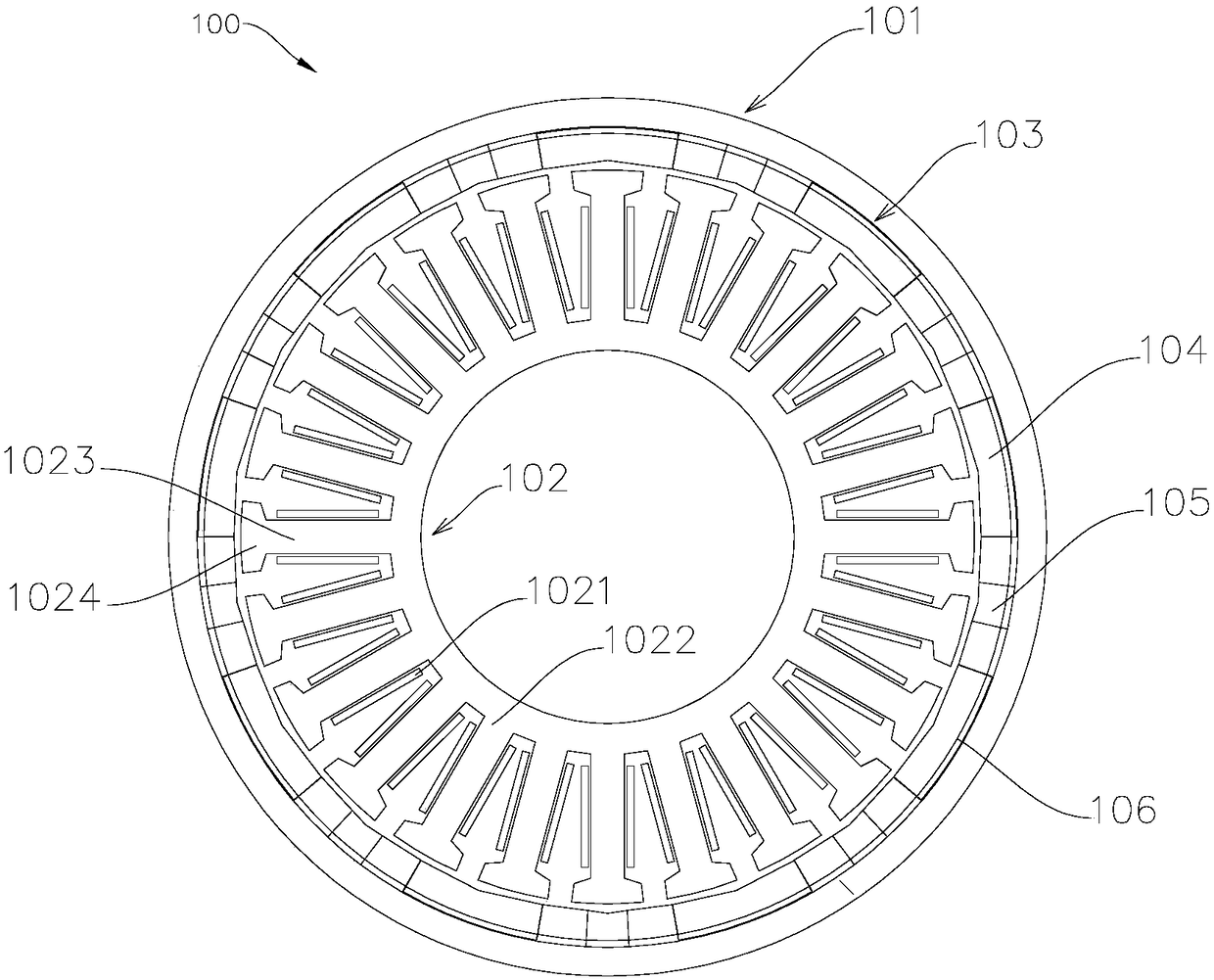
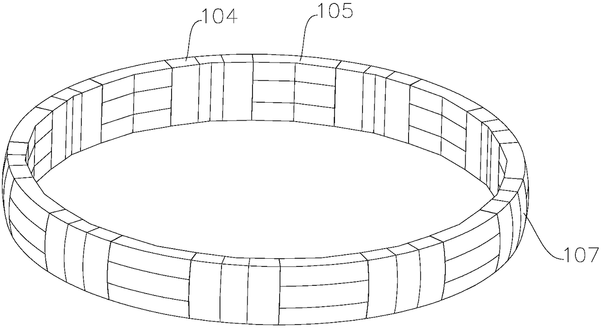
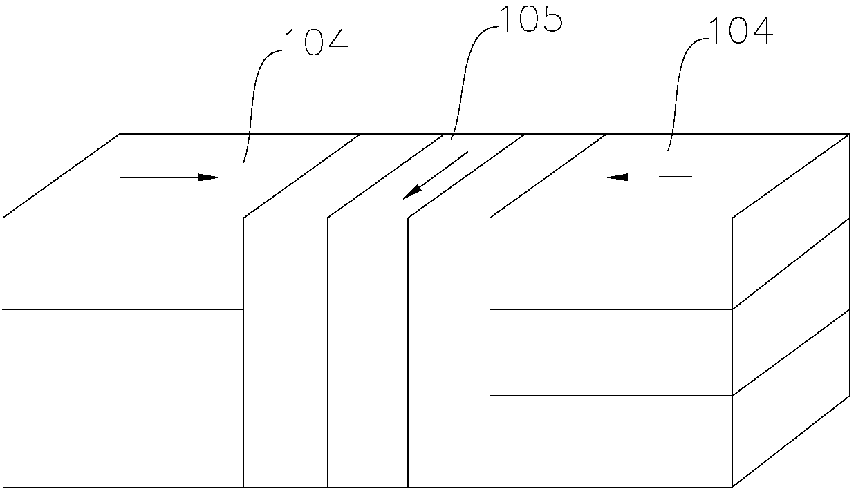
[0029] according to figure 1 , figure 2 Analysis, the motor 100 includes a rotor assembly 101 and a stator assembly 102 , the rotor assembly 101 is installed outside the stator assembly 102 , and a permanent magnet array 103 is fixed on the rotor assembly 101 . The permanent magnet array 103 is composed of a predetermined number of magnet groups consisting of three permanent magnets. The magnet set includes a first magnet set 104 and a second magnet set 105 . The permanent magnets of the first magnet group 104 are arranged along the circumferential direction of the motor 100 . The permanent magnets of the second magnet group 105 are arranged along the axial direction of the motor 100 . Along the circumferential direction of the motor 100 , the first magnet group 104 and the second magnet group 105 are evenly spaced to form the permanent magnet array 103 of the motor 100 . Along the axial direction of the motor 100, the working surface 106 of the permanent magnet array 103...

no. 2 example

[0039] This embodiment is basically the same as the first embodiment, the difference is that teeth of different shapes are formed on the magnetic permeable element.

[0040] Such as Figure 9 , Figure 10 As shown, the magnetic permeable element 400 includes a tooth 401 , a crown 402 and a yoke 403 . The tooth width of the tooth 401 near the tooth crown 402 is greater than the tooth width of the tooth 401 near the yoke 403 . The tooth height of the tooth 401 close to the permanent magnet 404 is smaller than the tooth height of the tooth 401 close to the yoke 403 . At the same time, ensure that the cross-sectional area of ​​the part of the tooth 401 between the tooth crown 402 and the yoke 403 is equivalent. It is beneficial to expand the slot width of the magnetic permeable element 400, to increase the conductive cross-sectional area of ​​the winding, to increase the slot fullness rate, to increase the effective side length, to reduce resistance, to reduce copper consumptio...


PUM


Abstract

The invention provides an electric motor comprising a rotor assembly and a stator assembly, wherein a permanent magnet array is fixed on the rotor assembly, and the stator assembly is provided with awinding and a magnetic conductive element. The permanent magnet array is provided with a preset number of magnetic poles, each magnetic pole consists of a magnetic body group, and the magnetic body group consists of at least two permanent magnets. When an air gap of the electric motor is kept unchanged, a utilization rate of the permanent magnets can be improved, magnetic field intensity of the magnetic poles can be increased, air-gap flux density of the electric motor can be enhanced, and work efficiency of the electric motor can be increased. Weight reduction of the permanent magnets can befacilitated.

Description

technical field [0001] The invention relates to the field of motors, in particular to a motor with a novel magnetic circuit structure. Background technique [0002] A motor is a common driving device in daily life, which can convert electrical energy into mechanical energy. The motor includes a stator assembly and a rotor assembly, and the rotation of the rotor assembly relative to the stator assembly is realized by means of electromagnetic transformation, and the rotor assembly outputs power through a rotating shaft. In order to improve the power output of the motor, the magnetism of the permanent magnet is enhanced, and the air gap density of the motor is reduced. However, there is a certain degree of magnetization saturation in the permanent magnet, and the volume of the permanent magnet increases with the increase of the magnetization intensity, which increases the weight of the motor; if the air gap flux density of the motor is too small, there is greater safety. Con...

Claims


Application Information

Patent Timeline
Patent Type & Authority Applications(China)
IPC IPC(8): H02K1/27H02K1/14
CPCH02K1/146H02K1/2753H02K1/2786H02K2201/03
Inventor 何春旺
Owner ZHUHAI PANLEI INTELLIGENT TECH CO LTD
Why Eureka
Try Eureka