
Actuator

Pending Publication Date: 2022-03-24
HYOSUNG HEAVY IND CORP
View PDF0 Cites 1 Cited by
  • Summary
  • Abstract
  • Description
  • Claims
  • Application Information

AI Technical Summary

Benefits of technology

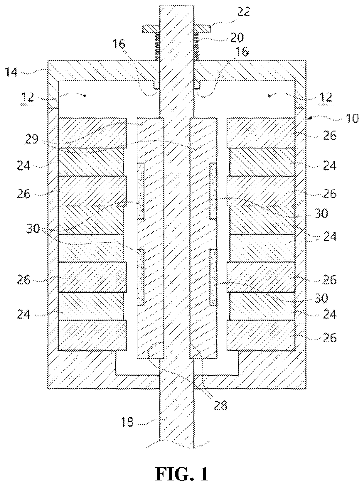
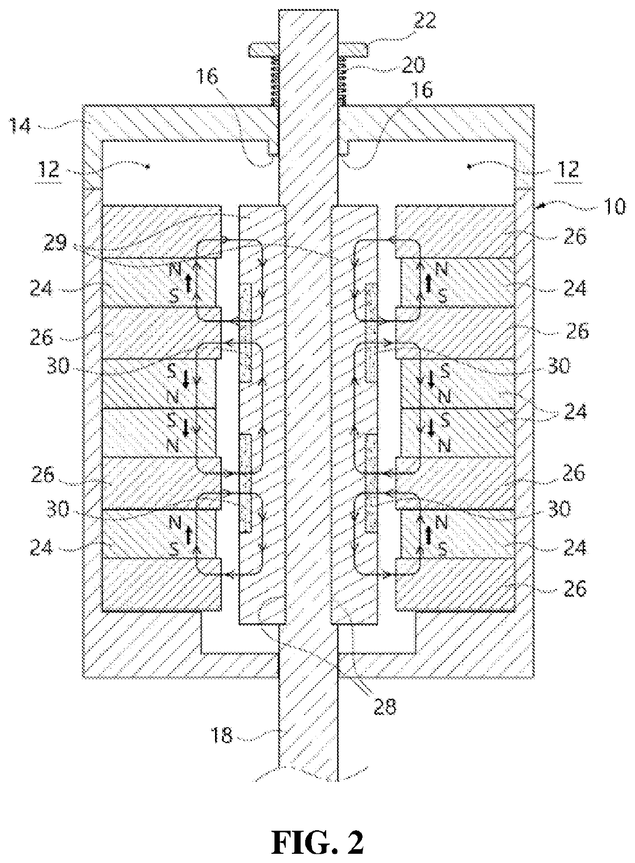
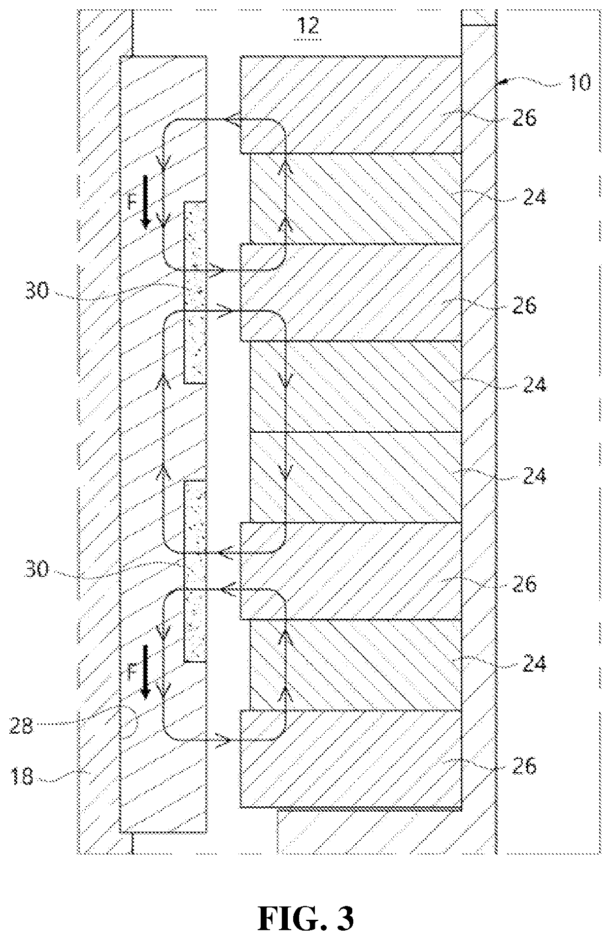
This patent describes an actuator that has a stronger magnetic field, which makes it easier to operate. The actuator includes a housing, an iron core, and a coil. By installing a permanent magnet on each side of the iron core and facing the coil, the actuator can generate more force and have a higher thrust. This design eliminates the need for a separate bobbin and reduces the size of the actuator. The actuator also has a reduced gap between the permanent magnet and coil, which simplifies the assembly process and reduces tolerances.

Problems solved by technology

In this case, there occurs a problem that the size of the actuator is increased.
However, when the bobbin is used, gaps occur between the inner surface of the bobbin and the permanent magnet and between the outer surface of the bobbin and the housing, so the entire size of the actuator is increased and tolerance management in which these gaps are required to be constant is difficult.

Method used


Image

  • Actuator
  • Actuator
  • Actuator

Examples


Embodiment Construction

[0027]Hereinafter, an embodiment of the present disclosure will be described in detail with reference to the accompanying drawings. In giving reference numerals to components of each drawing, it should be noted that the same components are given the same reference numerals as many as possible although they are indicated on different drawings. In addition, in describing the embodiment of the present disclosure, if it is determined that a detailed description of a related known configuration or function interferes with the understanding of the embodiment of the present disclosure, the detailed description thereof will be omitted.

[0028]In addition, in describing the components of an actuator of the present disclosure according to the embodiment, terms such as first, second, A, B, (a), (b), etc. may be used. These terms are only for distinguishing the components from other components, and the essence or order of the components are not limited by the terms. When it is described that a co...


PUM


Abstract

An actuator is proposed. A housing and a housing cap constitute an exterior of the actuator, and a driving pin is installed by passing through an inner space of the housing such that the driving pin moves rectilinearly. A permanent magnet and an outer iron core are stacked and installed at the inner surface of the housing, that is, in the inner space. The permanent magnets and the outer iron core are stacked such that a set of permanent magnet and outer iron core in which the permanent magnet is stacked at each of opposite sides of one outer iron core.

Description

TECHNICAL FIELD[0001]The present disclosure relates generally to an actuator. More particularly, the present disclosure relates to an actuator in which a rectilinear movement of a driving pin is performed by using a permanent magnet and a coil.BACKGROUND ART[0002]In actuators, there is a type of actuator which uses a voice coil to drive a driving pin. The actuator using the voice coil is driven in a principle in which force (Lorentz force) is generated in a conducting wire when electric current flows through the conducting wire in a magnetic field.[0003]That is, when the strength of the magnetic field is B, electric current flowing in the conducting wire is i, and the entire length of the conducting wire inside the magnetic field is L, force F generated in the conducting wire is expressed by the following equation.F=BiL(N)[0004]Here, the force generated in the conducting wire is directed perpendicularly to electric current flowing in the magnetic field and the conducting wire. The d...

Claims


Application Information

Patent Timeline
IPC IPC(8): H02K33/06
CPCH02K33/06H02K41/031H02K5/04H02K11/0141
Inventor KIM, DO JINSIM, DONG JOONLEE, SUNG HO
Owner HYOSUNG HEAVY IND CORP
Learn More