
Camera Module

a technology of camera module and camera body, which is applied in the field of camera module, can solve the problems of conventional camera module having a difficulty in obtaining a high-quality digital imag

Active Publication Date: 2012-12-06
LG INNOTEK CO LTD
View PDF9 Cites 29 Cited by
  • Summary
  • Abstract
  • Description
  • Claims
  • Application Information

AI Technical Summary

Benefits of technology

[0007]The present disclosure has been made to solve the foregoing problems of the prior art and therefore an object of certain embodiments of the present disclosure is to provide a camera module configured to greatly improve auto focusing and shaking correction function, and ease of assembly, and to inhibit hand-shaking correction function from being decreased by main circuit substrate applied with a driving signal.
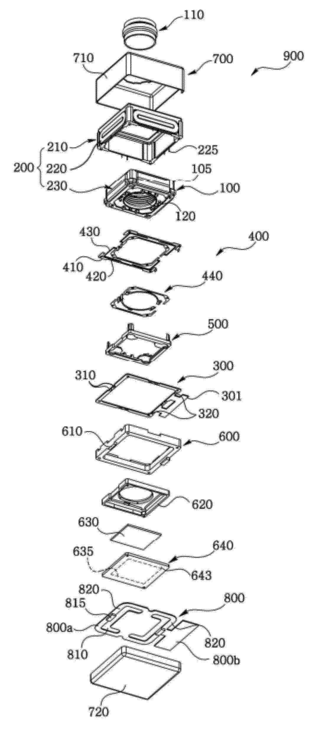
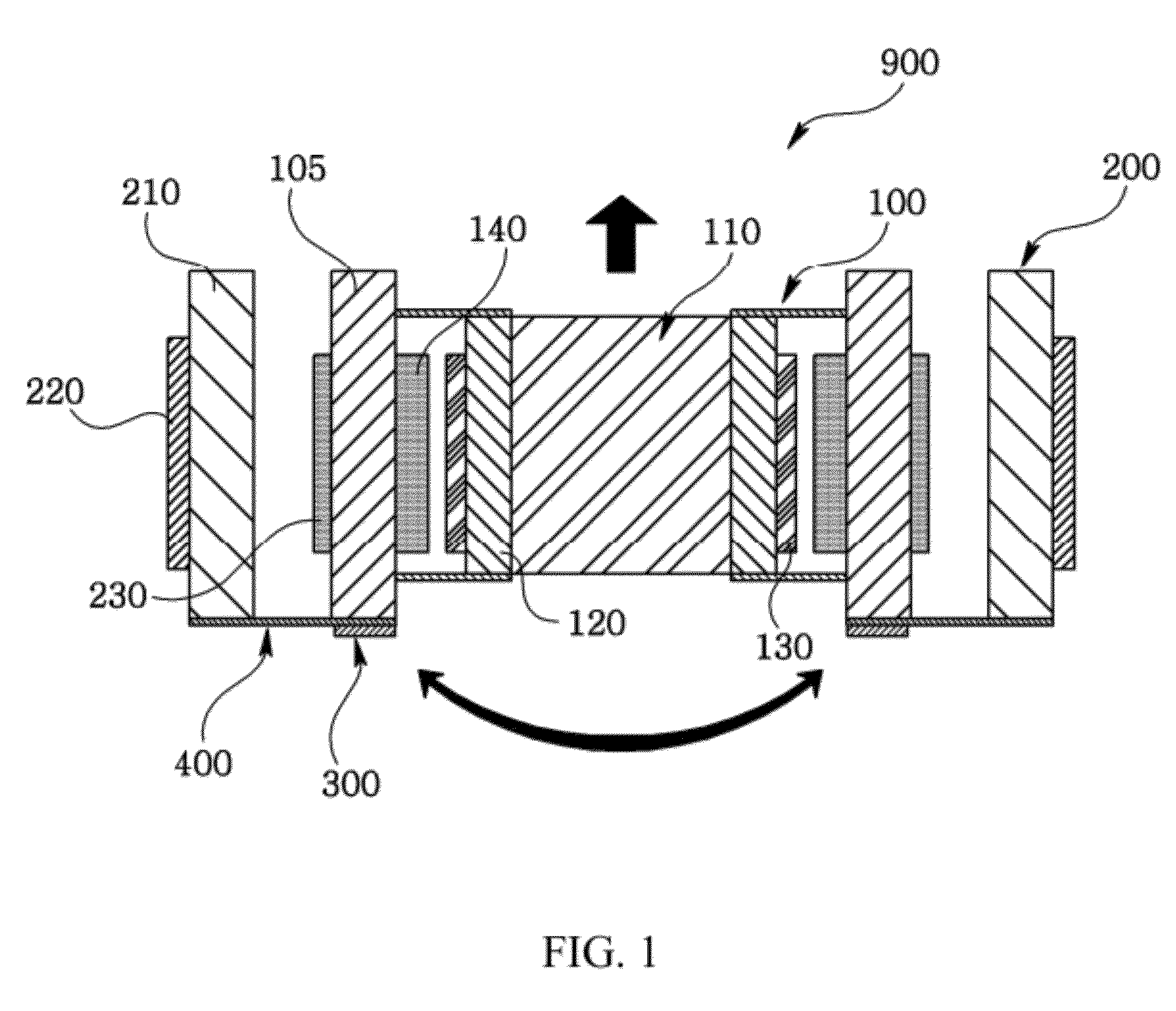
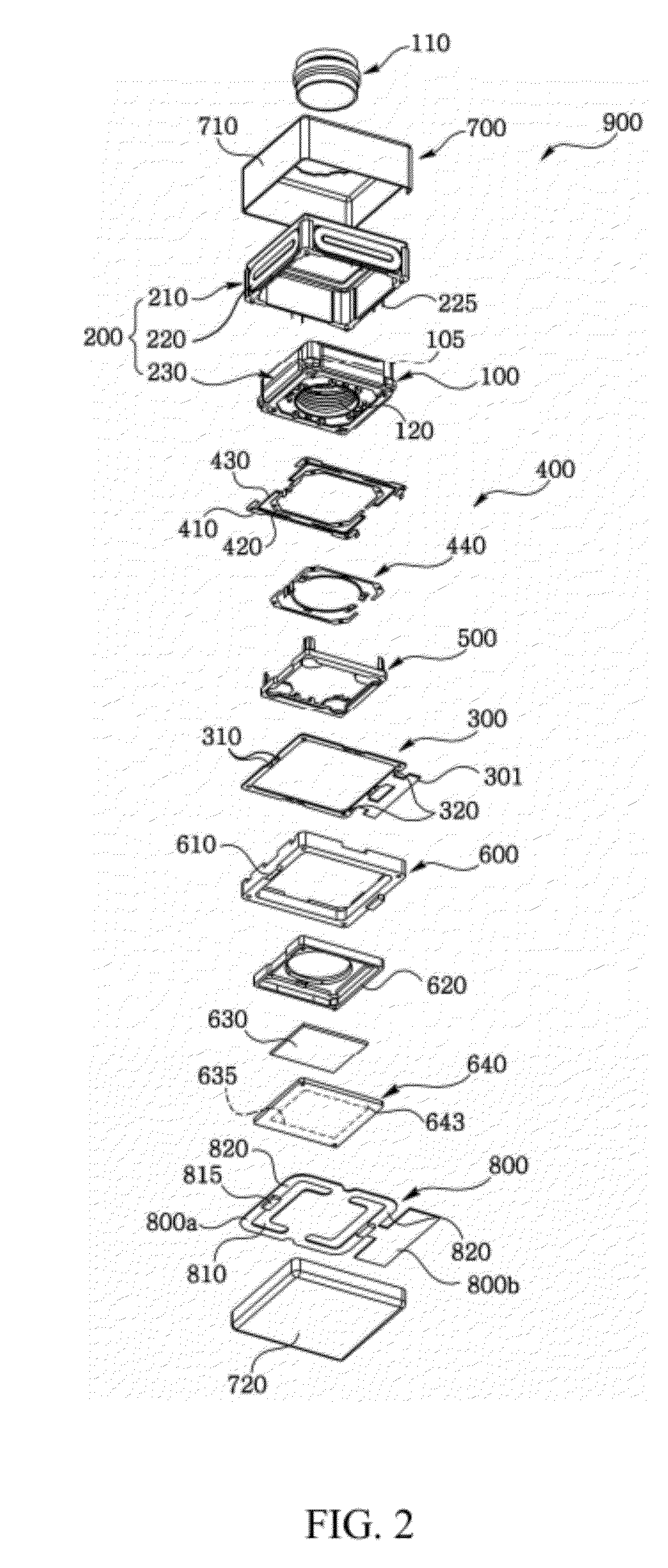
[0029]The camera module according to the present disclosure has an advantageous effect in that a lens is upped and downed by an auto focusing module, an auto focusing module is tilted by a hand-shaking correction module to perform hand-shaking correction, and an opening symmetrical to a main circuit substrate coupled to the auto focusing module is formed to inhibit a tilt operation fault of the auto focusing module.

Problems solved by technology

However, the conventional camera module has a difficulty in obtaining a high quality digital image due to lack of auto-focusing function capable of automatically adjusting a gap between the lens and the image sensor module and hand-shaking correction function in mobile phones, smart phones and smart pads.

Method used


Image

  • Camera Module
  • Camera Module
  • Camera Module

Examples


Embodiment Construction

[0036]Various exemplary embodiments will be described more fully hereinafter with reference to the accompanying drawings, in which some exemplary embodiments are shown. The present inventive concept may, however, be embodied in many different forms and should not be construed as limited to the example embodiments set forth herein. Rather, these exemplary embodiments are provided so that this description will be thorough and complete, and will fully convey the scope of the present inventive concept to those skilled in the art.

[0037]Unless otherwise defined, all terms (including technical and scientific terms) used herein have the same meaning as commonly understood by one of ordinary skill in the art to which this inventive concept belongs. It will be further understood that terms, such as those defined in commonly used dictionaries, should be interpreted as having a meaning that is consistent with their meaning in the context of the relevant art and will not be interpreted in an ide...


PUM


Abstract

The present disclosure relates to a camera module including: an auto focusing module upping and downing a lens; a hand-shaking correction module wrapping the auto focusing module to correct a hand-shaking by horizontally tilting the auto focusing module; a circuit substrate electrically connected to the hand-shaking correction module and the auto focusing module; a bottom case supporting the circuit substrate to be coupled to the auto focusing module; and a main circuit substrate secured to the bottom case to be electrically connected to the image sensor module, wherein the main circuit substrate is formed with oblong symmetrical openings along an edge of the main circuit substrate.

Description

CROSS-REFERENCE TO RELATED APPLICATION[0001]This application claims the benefit under 35 U.S.C. §119 of Korean Patent Application No. 10-2011-0054130, filed Jun. 3, 2011, which is hereby incorporated by reference in its entirety.BACKGROUND[0002]1. Field of the Invention[0003]The teachings in accordance with the exemplary embodiments of this present disclosure generally relate to a camera module applicable to a smart phone.[0004]2. Background[0005]Recently, a mobile phone, a smart phone and a smart pad which is a type of portable personal computer, mounted with a camera module capable of storing an object in a digital image or a moving image, have been developed.[0006]A conventional camera module includes a lens and an image sensor module converting light having passed the lens to a digital image. However, the conventional camera module has a difficulty in obtaining a high quality digital image due to lack of auto-focusing function capable of automatically adjusting a gap between the...

Claims


Application Information

Patent Timeline
IPC IPC(8): H04N5/232H04N5/225
CPCH04N5/23287H04N5/2254H04N23/50H04N23/687H04N23/00
Inventor HAN, JINSUK
Owner LG INNOTEK CO LTD
Learn More