Technique for Telescope Polar Alignment

a technology of polar alignment and telescope, which is applied in the field of polar alignment of astronomical telescope mounts, can solve the problems of poor alignment, affecting the apparent position of polar alignment stars, and promoting more accurate polar alignment, accurately placing polar alignment, and accurately judging the angular distance across the reticl

Inactive Publication Date: 2012-12-06
XU NING +1
View PDF6 Cites 11 Cited by
  • Summary
  • Abstract
  • Description
  • Claims
  • Application Information

AI Technical Summary

Benefits of technology

[0018]The inventors hereof have developed a novel technique for promoting more accurate polar alignment. The technique involves providing a polar scope having a reticle that includes multiple inscribed declination circles spaced apart from one another by at most 10 arc-minute intervals. The multiple circles allow users to accurately judge angular distance across the reticle and therefore accurately place the polar alignment object, whose apparent position may vary, relative to the circles on the reticle. In one aspect, a controller is provided to indicate the position of the polar alignment object. The indicated position includes corrections for any of proper motion, precession, or atmospheric refraction of the polar alignment object.

Problems solved by technology

Second, the apparent position of a polar alignment star is affected by the atmosphere.
Atmospheric refraction can alter the apparent position of polar alignment stars, causing poor alignment to occur even when star positions as viewed through the polar scope appear to be correct.

Method used


Image

  • Technique for Telescope Polar Alignment
  • Technique for Telescope Polar Alignment
  • Technique for Telescope Polar Alignment

Examples


Embodiment Construction

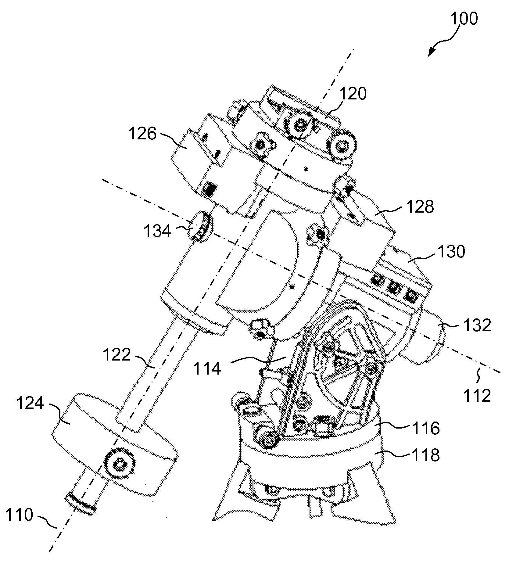
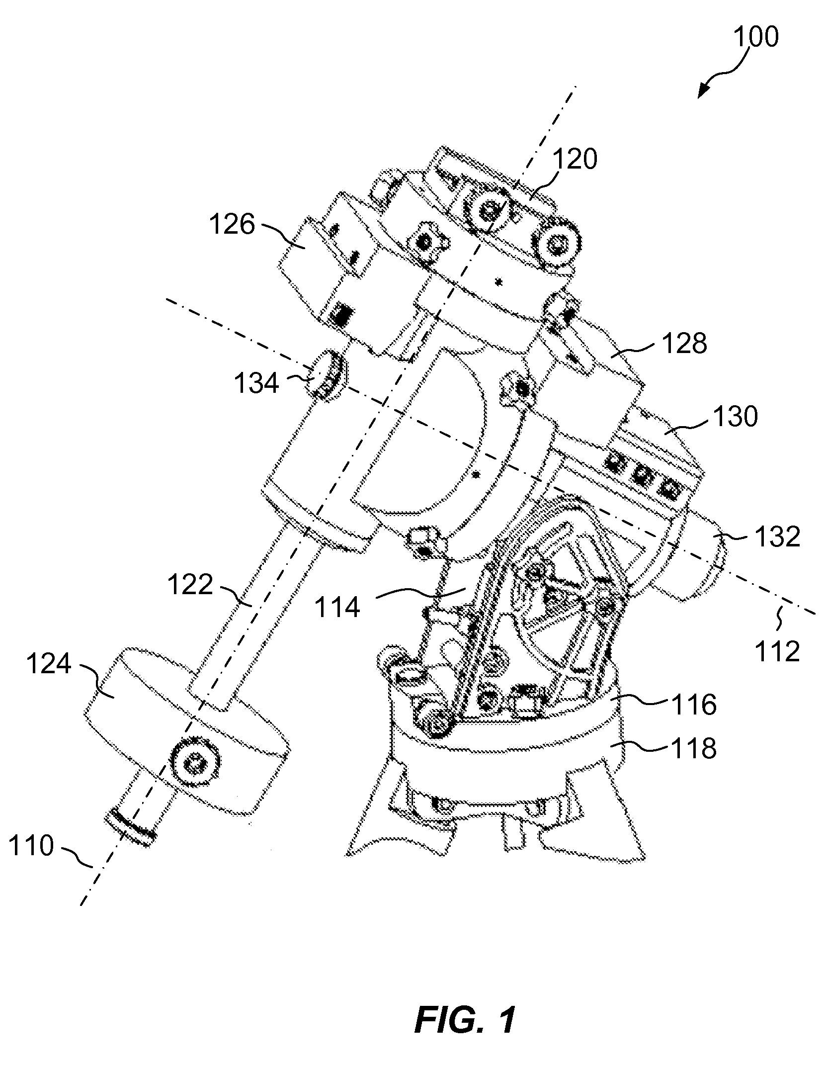
[0026]FIG. 2 shows an example of a polar scope 200, which may be provided in accordance with embodiments of the invention. The polar scope 200 may include an objective lens 210, an ocular 212, and a reticle 214. These may be axially aligned and held in place within a tube 218. In one example, the polar scope 200 may be provided as part of the equatorial mount 100 concentric with the right ascension axis 112 of the mount. In another example, the polar scope 200 may be attached to the mount parallel to the right ascension axis but not concentric therewith.

[0027]The objective lens 210 may be a single element lens or a compound lens, such as an achromatic or apochromatic lens. The objective lens 210 has a focal length representing the distance from the objective at which focused images of distant objects may be produced.

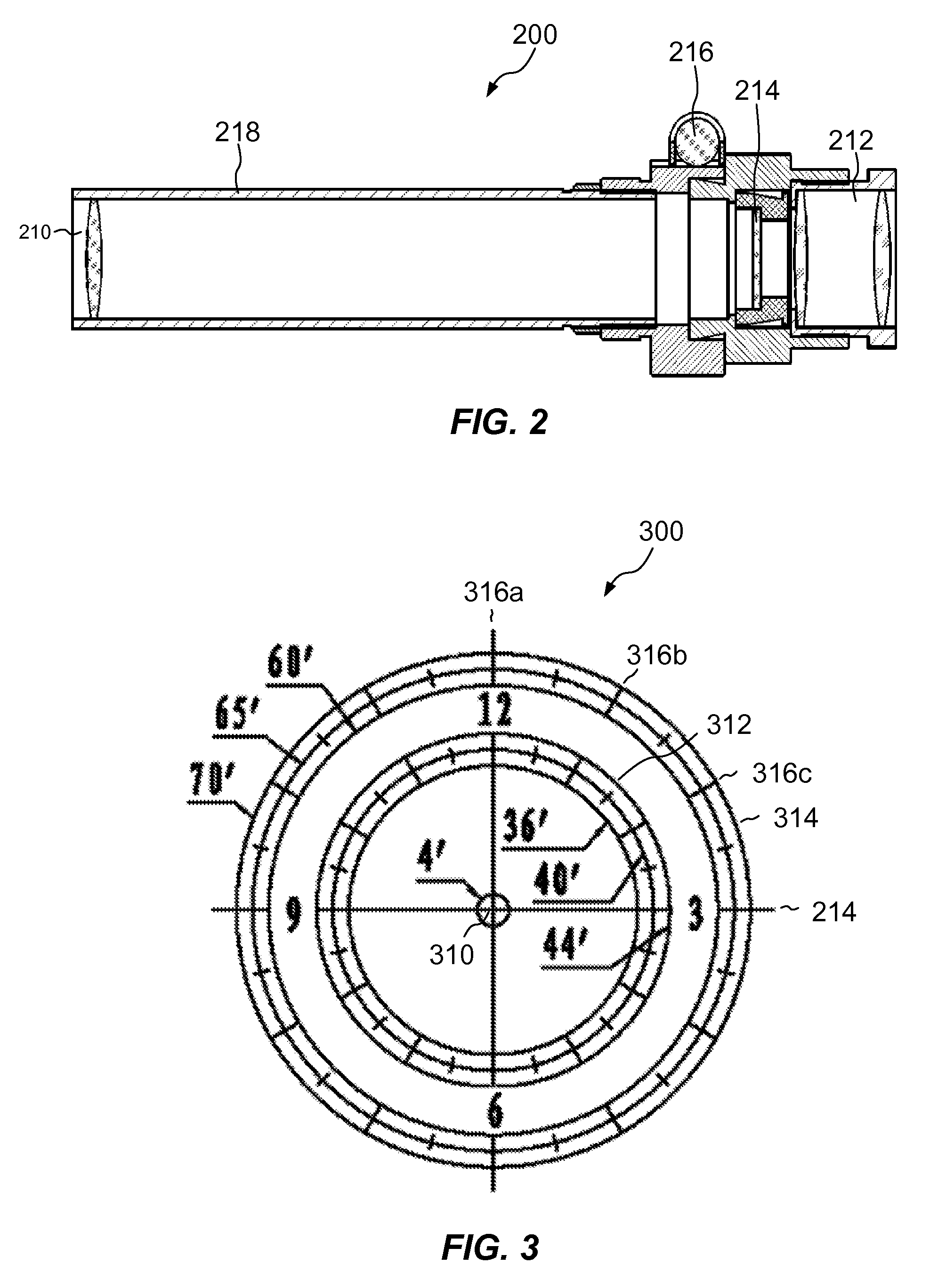
[0028]The reticle 214 is preferably positioned at a distance from the objective lens 210 that equals the objective's focal length. The reticle 214 may have the shape of ...


PUM


Abstract

A polar scope for a telescope mount includes a reticle having a pattern with multiple markings that allows users to accurately position pole stars for precise polar alignment. A system and mount may be provided including a polar scope of this kind. The polar scope may be provided with a controller that calculates the apparent position of a pole star, while accounting for errors, such as proper motion, precession of the earth's axis, and/or atmospheric refraction.

Description

CROSS-REFERENCES TO RELATED APPLICATIONS[0001]Not Applicable.STATEMENT REGARDING FEDERALLY SPONSORED RESEARCH OR DEVELOPMENT[0002]Not Applicable.NAMES OF PARTIES TO A JOINT RESEARCH AGREEMENT[0003]Not ApplicableREFERENCE TO A “SEQUENCE LISTING,” A TABLE, OR A COMPUTER PROGRAM LISTING APPENDIX[0004]Not Applicable.BACKGROUND OF THE INVENTION[0005]1. Field of the Invention[0006]This invention relates generally to astronomical telescopes, and, more particularly, to polar alignment of astronomical telescope mounts.[0007]2. Description of Related Art[0008]Astronomical telescopes are essential observing equipment for professional and amateur astronomers alike. Telescopes are available in a wide variety of optical types, including refracting, reflecting, and catadioptric systems, and with a wide variety of mounts, including altazimuth, equatorial, and spherical mounts.[0009]Both altazimuth and equatorial mounts allow telescopes to rotate about two perpendicular axes. In a typical altazimuth...

Claims


Application Information

Patent Timeline
Patent Type & Authority Applications(United States)
IPC IPC(8): G02B23/16G02B23/00
CPCG02B23/16
Inventor XU, NINGXU, WEN
Owner XU NING
Why Eureka
Try Eureka