Maintaining member, module, and electronic apparatus

a technology of electronic equipment and main body, which is applied in the direction of instruments, machine supports, other domestic objects, etc., can solve the problems of increasing the size of the sensor device, difficulty in mounting the sensor device directly on the circuit board, etc., and achieves the effect of high reliability

Active Publication Date: 2012-12-06
SEIKO EPSON CORP
View PDF5 Cites 21 Cited by
  • Summary
  • Abstract
  • Description
  • Claims
  • Application Information

AI Technical Summary

Benefits of technology

[0046]According to this configuration, an electron

Problems solved by technology

In the case of mounting these sensor devices on a circuit board or the like, directly mounting the sensor devices on the circuit board is difficult, and the sensor devices are generally mounted in a

Method used


Image

  • Maintaining member, module, and electronic apparatus
  • Maintaining member, module, and electronic apparatus
  • Maintaining member, module, and electronic apparatus

Examples


first embodiment

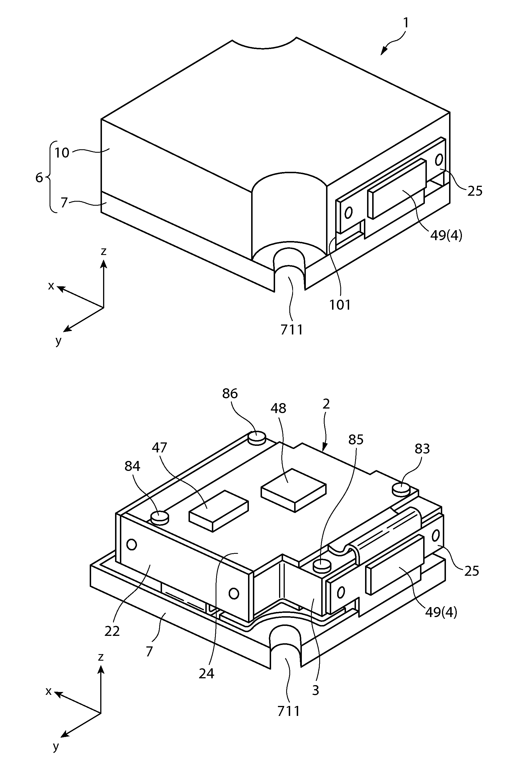
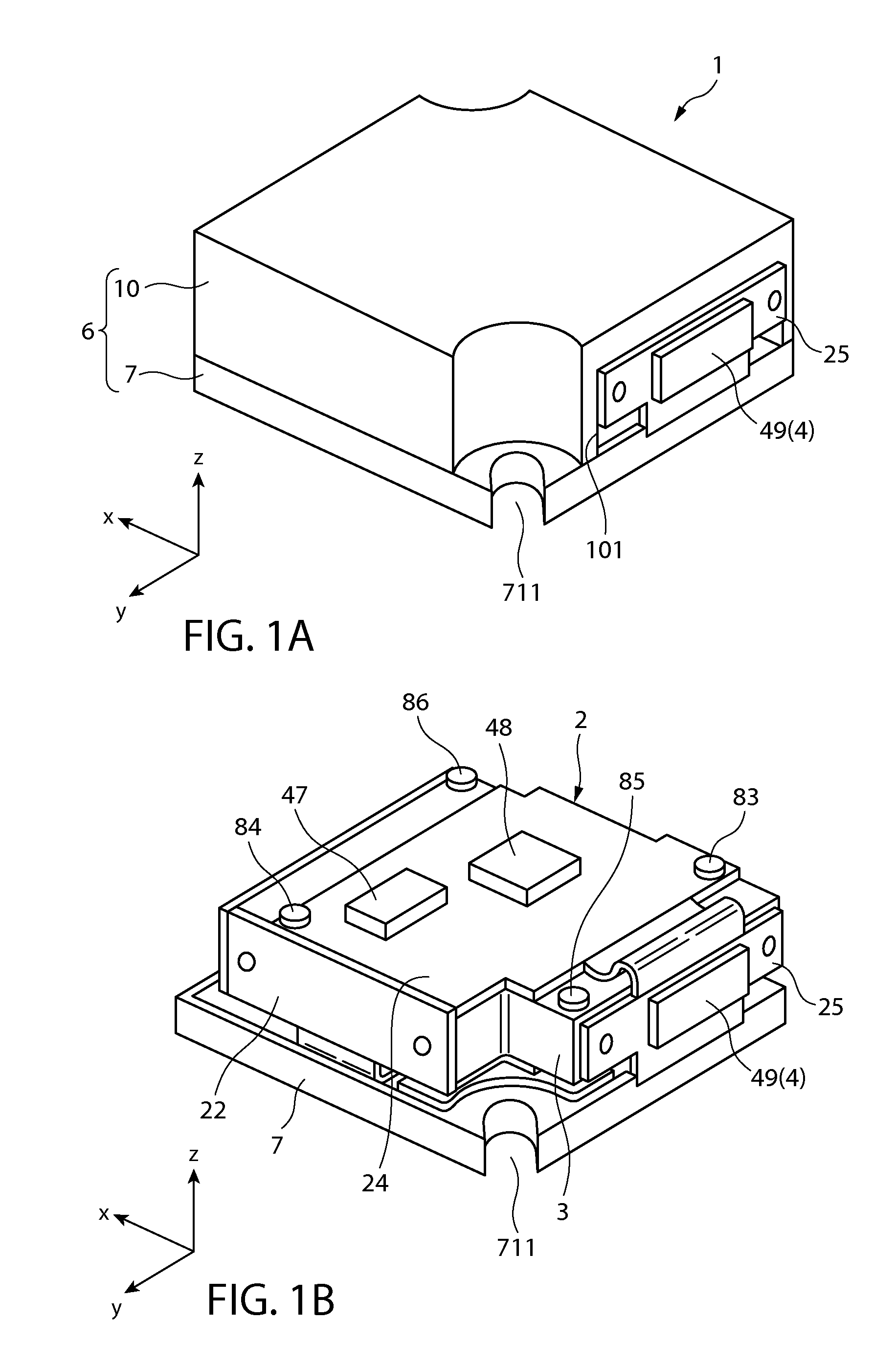
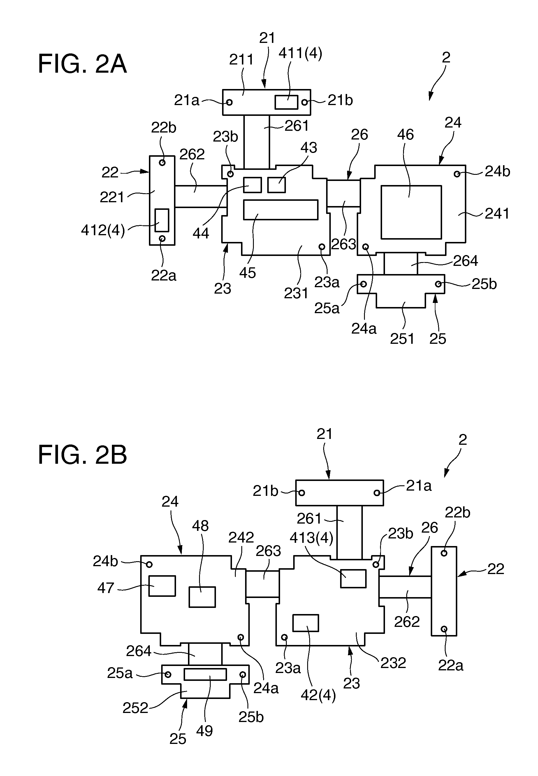
[0060]FIGS. 1A and 1B show perspective views illustrating a very suitable embodiment of a module according to the invention, FIGS. 2A and 2B show development views of amounting substrate provided to the module shown in FIGS. 1A and 1B, FIG. 3 shows a perspective view illustrating a state in which the mounting substrate shown in FIGS. 2A and 2B is assembled, FIG. 4 shows a plan view illustrating an example of an angular velocity sensor provided to the module shown in FIGS. 1A and 1B, FIGS. 5A and 5B show perspective views illustrating a supporting member provided to the module shown in FIGS. 1A and 1B, FIG. 6 shows a transverse cross-sectional view illustrating the supporting member to which the mounting substrate is fixed, FIGS. 7A and 7B show perspective views illustrating the supporting member to which the mounting substrate is fixed, FIG. 8 shows a perspective view illustrating the maintaining member provided to the module shown in FIGS. 1A and 1B, and FIG. 9 shows a plan view il...


PUM


Abstract

A maintaining member includes alignment portions that determine a maintaining position of a module, in which each of the alignment portions has a mounting face to fix the module. When the maintaining member is partitioned into a first region to a fourth region by a first axis and a second axis that are orthogonal to each other in plan view with respect to the center of the maintaining member, the alignment portions are provided at the regions one by one.

Description

BACKGROUND[0001]1. Technical Field[0002]The present invention relates to a maintaining member, a module, and an electronic apparatus.[0003]2. Related Art[0004]For example, a sensor unit disclosed in U.S. Pat. No. 7,040,922 is known. The sensor unit disclosed in U.S. Pat. No. 7,040,922 is provided with a mounting member that has a rectangular parallelepiped shape and three faces orthogonal to each other, and sensor devices mounted on the three faces, respectively.[0005]In the case of mounting these sensor devices on a circuit board or the like, directly mounting the sensor devices on the circuit board is difficult, and the sensor devices are generally mounted in a state of being accommodated in a casing including a maintaining member and a cover member. However, when the sensor devices are accommodated in this casing, the size of the sensor devices may increase. In addition, when the sensor devices are fixed in an inclined state with respect to the casing, detection axes of the senso...

Claims


Application Information

Patent Timeline
IPC IPC(8): H05K7/02F16M13/00
CPCG01D11/30
Inventor SAKUMA, MASAYASUKOBAYASHI, YOSHIHIROKITAMURA, SHOJIROCHINO, TAKETOOGAMI, MICHIHARU
Owner SEIKO EPSON CORP
Why Eureka
Try Eureka