Machine for forming at least one crease on cover before attachment to book binding

Inactive Publication Date: 2012-12-06
HORIZON INTERNATIONAL INC
View PDF10 Cites 10 Cited by
  • Summary
  • Abstract
  • Description
  • Claims
  • Application Information

AI Technical Summary

Benefits of technology

[0075]According to the present invention, the cover is fed between the pairs of first and second feed rollers which synchronously rotate in the same direction, the creasing unit composed of the fixed and movable dies is disposed between the pairs of first and second feed rollers, the fixed and movable dies are disposed opposite to each other and with the feed path of the cover therebetween, and the sensor is disposed for detecting the front end of the cover between the pair of first feed rollers and the creasing unit. Further, the pairs of first and second feed rollers are stopped, the creasing unit is operated and the movable die is pressed on the fixed die every time the cover is fed by the predetermined length from the sensor, thereby at least one crease is formed on the cover. As a result, the pairs of first and second feed rollers are stopped and the creasing unit is operated every time the cover area to be provided with the crease is arrived at the position of the dies of the creasing unit while the cover is fed between the pairs of first and second

Problems solved by technology

Therefore, in the case that the cover is thick or relatively hard, the cover cannot be folded completely, which leads to a problem that the beautiful spine of the book with sharp corners cannot be obtained.
However, when various kinds of books of different thickness are produced in small lots, it is necessary to move the pair of first creasing rollers so as to change the distance between the pairs of first and second r

Method used


Image

  • Machine for forming at least one crease on cover before attachment to book binding
  • Machine for forming at least one crease on cover before attachment to book binding
  • Machine for forming at least one crease on cover before attachment to book binding

Examples


Embodiment Construction

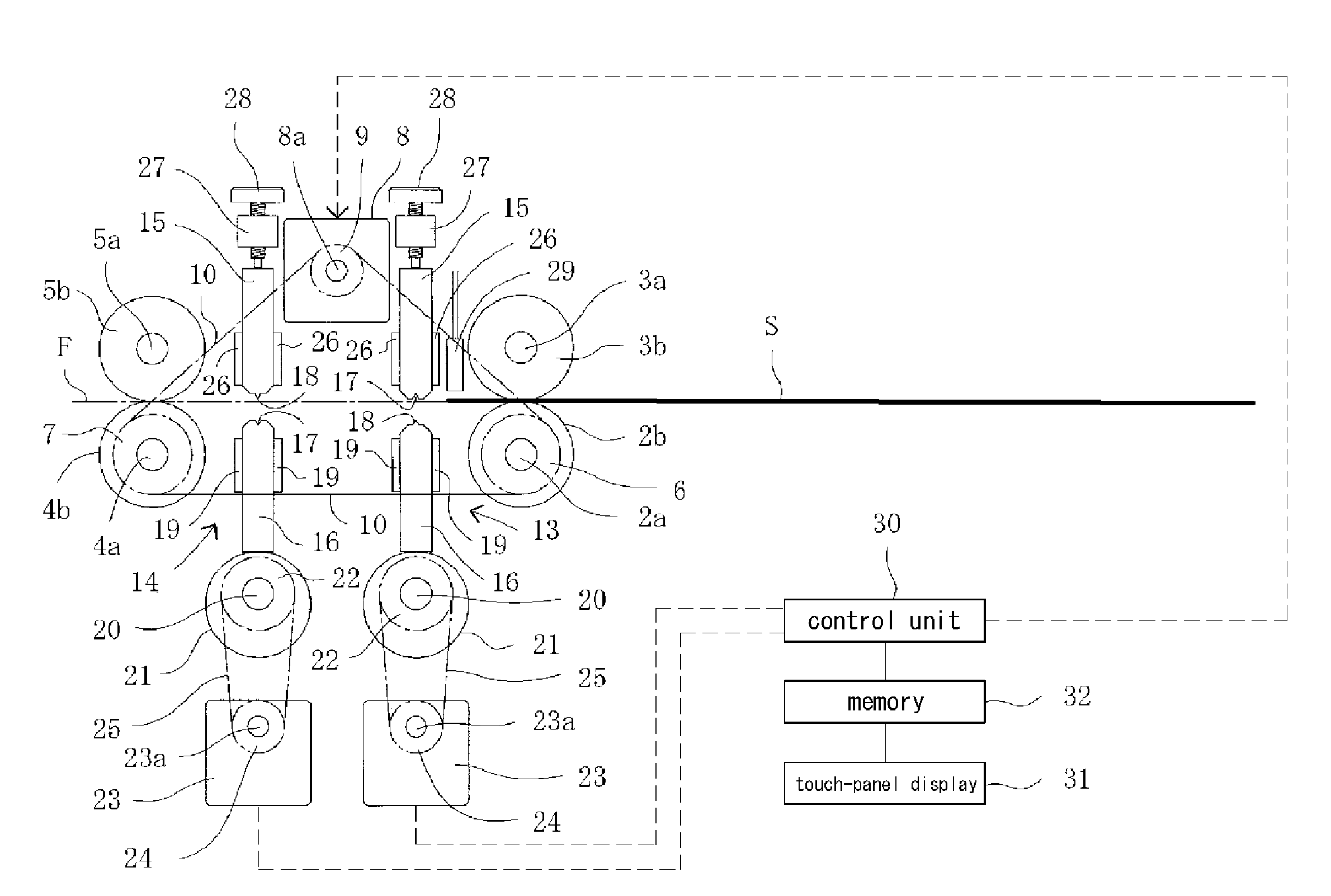
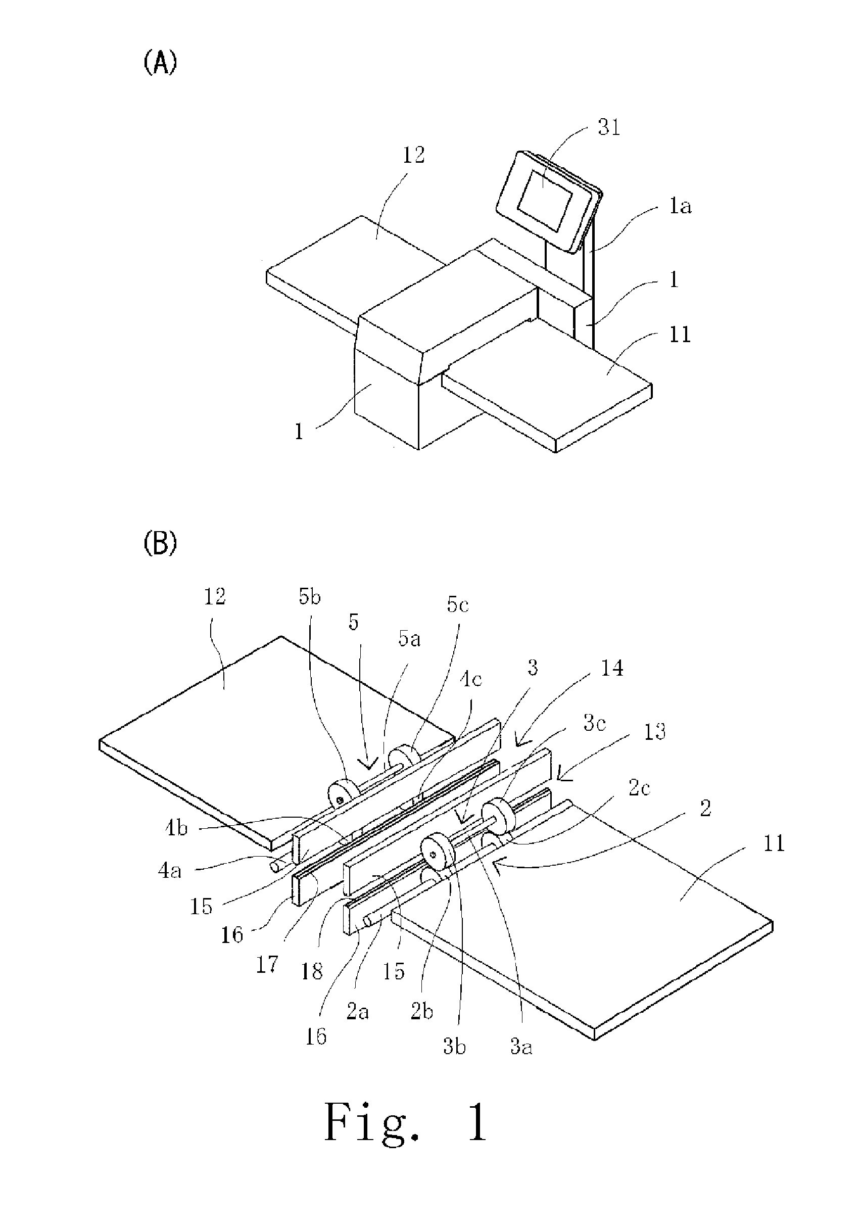
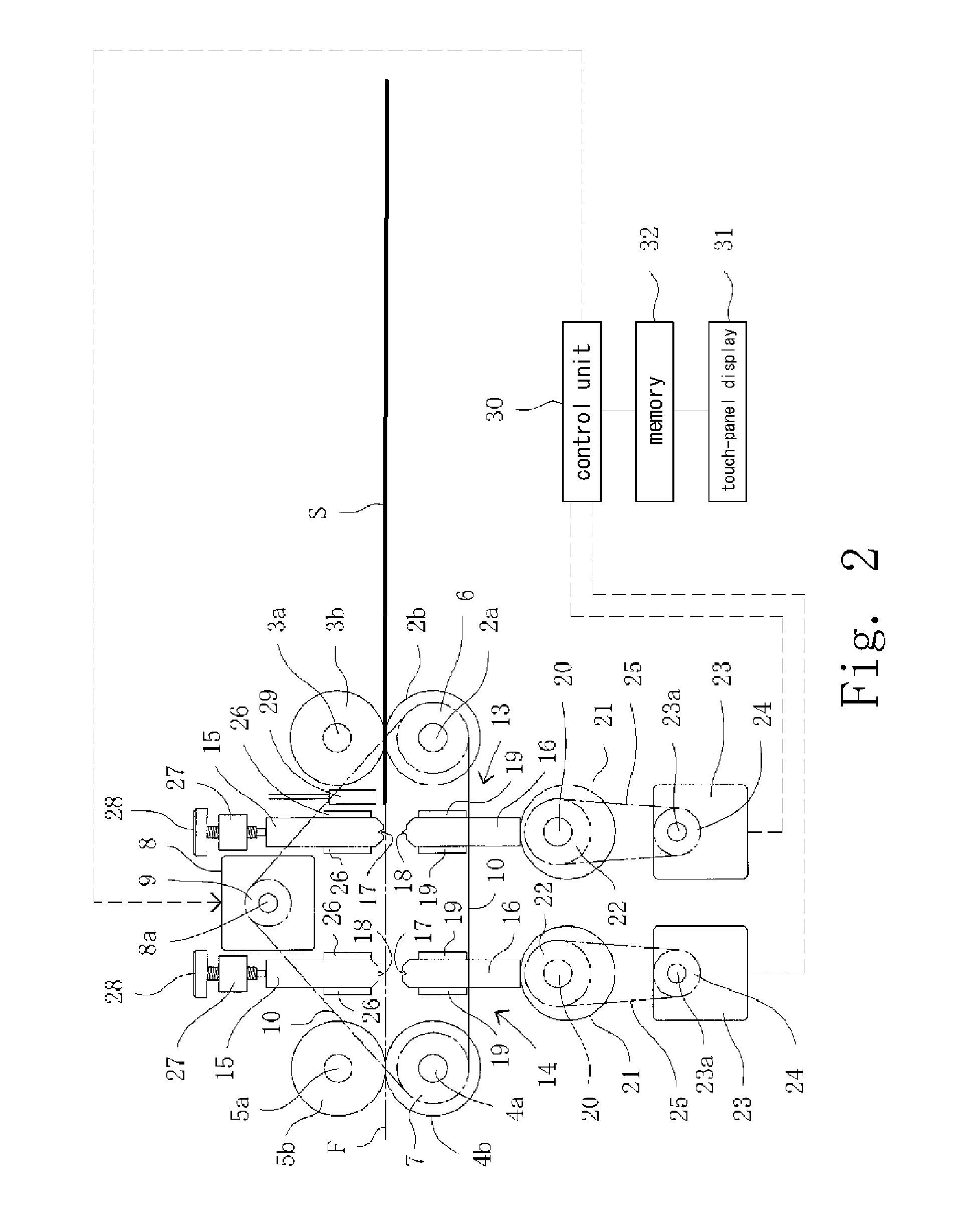
[0085]A preferred embodiment of the present invention will be explained below with reference to the accompanying drawings. FIG. 1A is a perspective view showing the machine according to one embodiment of the present invention. FIG. 1B is a perspective view showing the machine of FIG. 1A, in which the frame, a body cover, the drive mechanisms and so on are removed. FIG. 2 is a perspective view showing a schematic structure of main elements of the machine of FIG. 1.

[0086]The machine of the present invention is used in a perfect book binding process. As shown in FIGS. 6A-6C, for example, the cover S has a front-cover-forming area 51, a back-cover-forming area 52 and a spine-forming area 50 disposed therebetween. Further, as shown in FIGS. 6D-6F, the cover S has at least one turn-back area 53a, 53b outside of the front-cover-forming area 51 and / or the back-cover-forming area 52 together with the spine-forming area 50, the front-cover-forming area 51 and the back-cover-forming area 52. I...


PUM


Abstract

A cover S is fed between pairs of first and second feed rollers 2, 3; 4, 5 which synchronously rotate in the same direction, each of first and second creasing units 13, 14 composed of a fixed die 15 and a movable die 16 is disposed between the pairs of first and second feed rollers, the fixed and movable dies are opposite to each other and with a feed path F of the cover therebetween, a sensor 29 is disposed between the pair of first feed rollers 2, 3 and the first creasing unit 13 for detecting a front end of the cover, rotation number of the pairs of first and second feed rollers is controlled, the pairs of first and second feed rollers are stopped, the creasing unit is operated, and the movable die is pressed on the fixed die every time the cover is fed by a predetermined length from the sensor so that at least one crease is formed on the cover.

Description

TECHNICAL FIELD OF THE INVENTION[0001]The present invention relates to a machine for forming at least one crease on a cover before attachment to a book block in a perfect book binding process, the cover has a front-cover-forming area, a back-cover-forming area and a spine-forming area disposed therebetween, the spine-forming area of the cover is attached to a spine of the book block, and thereafter the cover is folded.BACKGROUND OF THE INVENTION[0002]A conventional perfect book binding apparatus, for example, comprises: a series of process units (a milling unit, a gluing unit and a cover attachment unit) arranged along a book block feed path for performing a book binding process; a clamp unit arranged for driving reciprocal movement along the book block feed path; and a clamp unit drive mechanism for reciprocal movement of the clamp unit. The clamp unit has a pair of clamp plates. The perfect book binding process is performed while the book block clamped by the clamp plates is seque...

Claims


Application Information

Patent Timeline
IPC IPC(8): B42C11/04
CPCB42C7/005B42D1/04B42C11/02B31F1/08
Inventor NONOSHITA, AKIRATAKAI, SHINICHIKOJIMA, NOBUYUKIWAKIMOTO, SHIGERUYOKOGI, TAKEHITO
Owner HORIZON INTERNATIONAL INC
Why Eureka
Try Eureka