Method and apparatus for determining a spatial positioning of loading equipment

a technology for determining the spatial positioning and loading equipment, which is applied in the direction of mechanical machines/dredgers, instruments, transportation and packaging, etc., can solve the problems of limited field of view or perspective, damage to the loading equipment, operator's view of the operating implement and surrounding environment may be restricted, etc., to facilitate remote monitoring of the operation of loading equipmen

Active Publication Date: 2012-12-06
MOTION METRICS INT CORP
View PDF3 Cites 45 Cited by
  • Summary
  • Abstract
  • Description
  • Claims
  • Application Information

AI Technical Summary

Problems solved by technology

However, the operator's view of the operating implement and surrounding environment may be constrained by a limited field of view or perspective due to the operator's location in a cab of the loading equipment.
Collision between loading equipment and objects or obstacles in the surrounding environment is a serious safety concern, and may also result in damage to the loading equipment.
It is also possible that an operator may overload and overstress the operating components of loading equipment by subjecting the equipment to excessive forces, due to a lack of feedback from the controls.
(1) They usually require re-initiation from time to time to calibrate the system as they may rely on signals generated by sensors such as potentiometers or resolvers, for example. When the loading equipment is powered down, the calibration information may be lost and the system will require recalibration.
(2) Mining shovels also typically operate in a harsh environment in which there is high likelihood of sensors on the operating components being damaged due to impact or due to ingress of dirt and debris. Systems that rely on signals produced from a plurality of sensors disposed at different locations on key components of the equipment are particularly prone to failure.

Method used


Image

  • Method and apparatus for determining a spatial positioning of loading equipment
  • Method and apparatus for determining a spatial positioning of loading equipment
  • Method and apparatus for determining a spatial positioning of loading equipment

Examples


Embodiment Construction

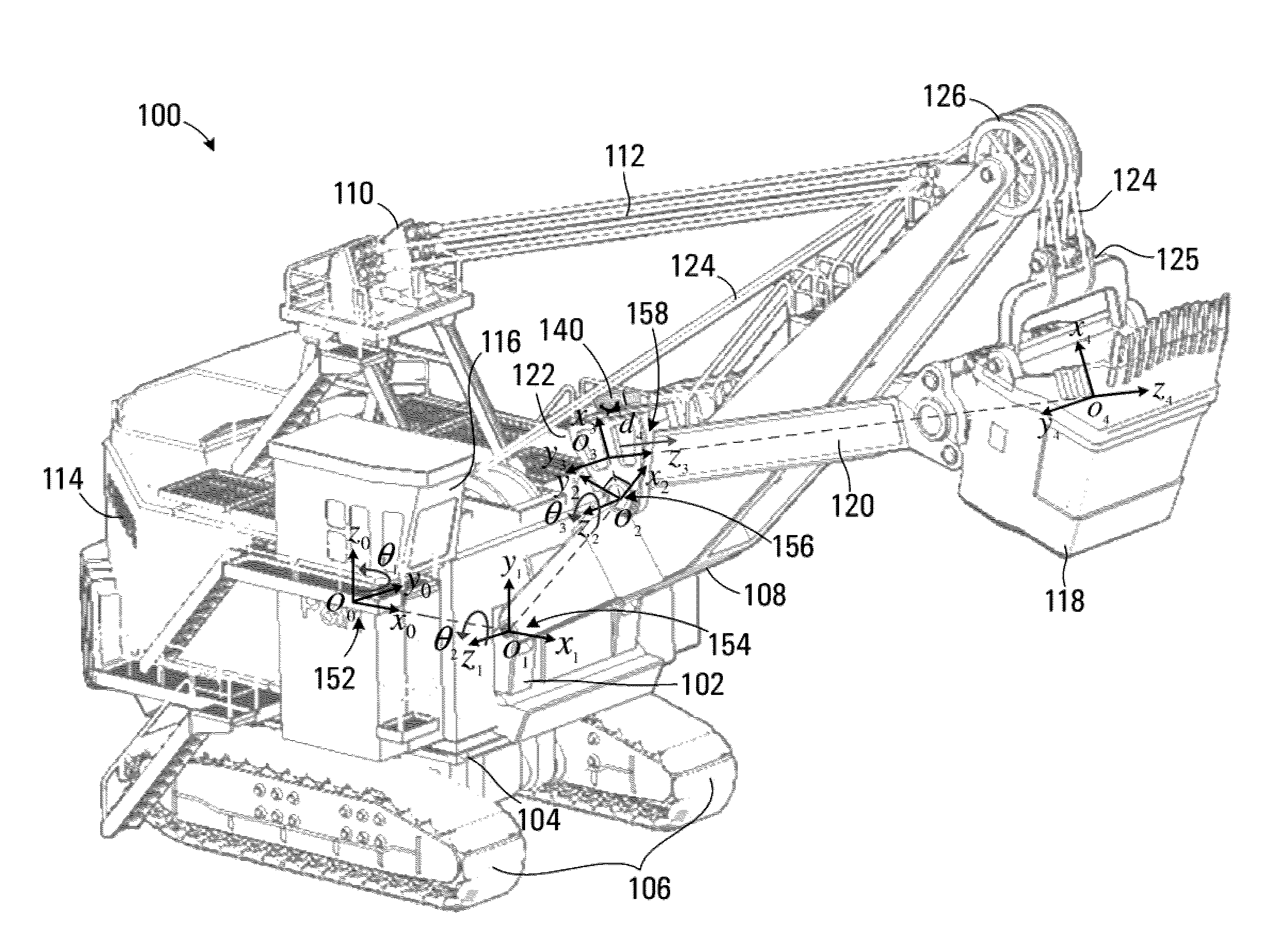
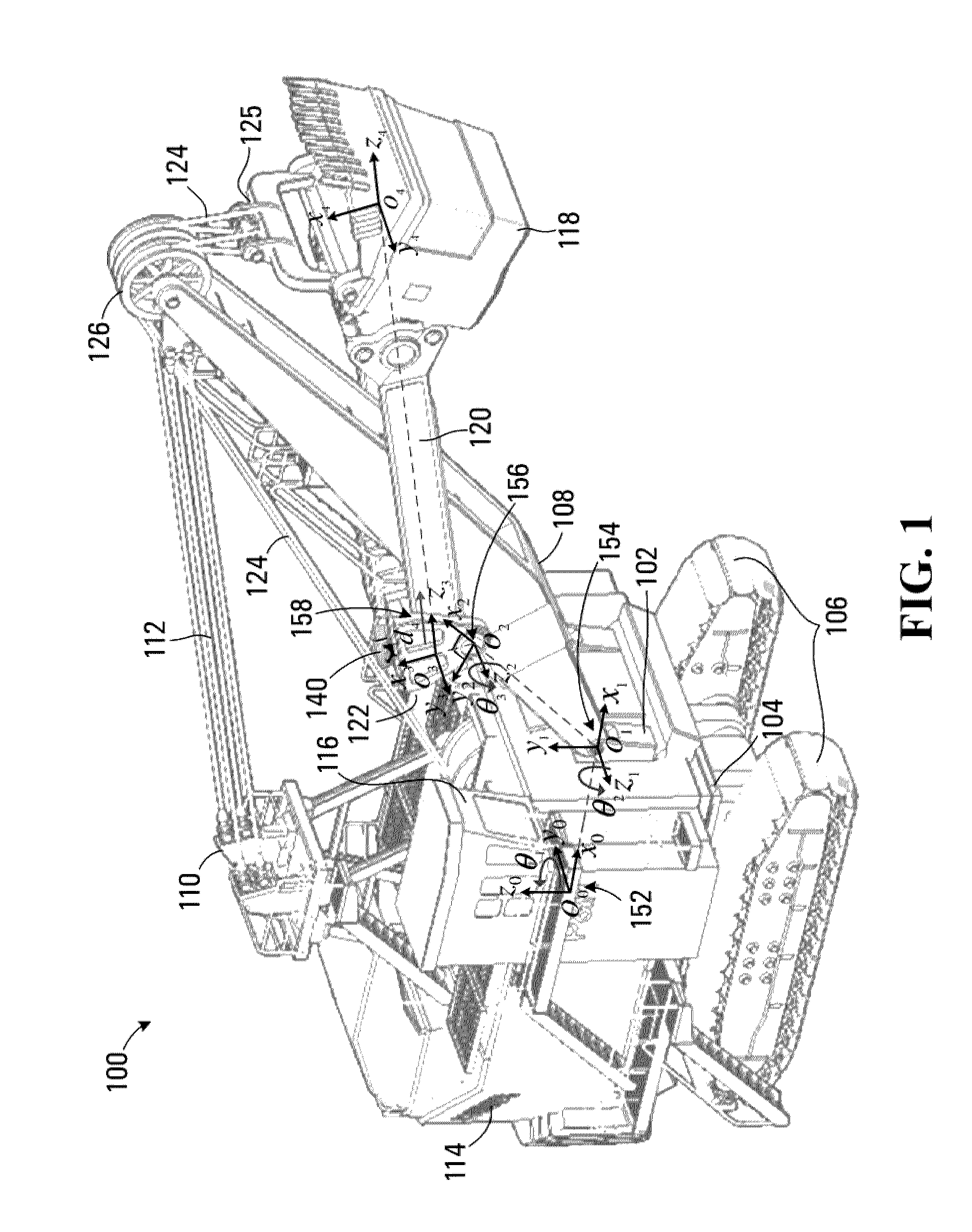
[0075]Referring to FIG. 1, an electric mining shovel is shown generally at 100. The mining shovel 100 includes a frame 102 pivotably mounted on a crawler platform 104. The crawler platform 104 includes crawler tracks 106 for moving the mining shovel 100 to a loading location. The mining shovel 100 also includes a boom 108, pivotably supported on frame 102, and an A-frame structure 110 attached to the frame 102. The boom 108 is supported by a boom suspension cable 112. During operation, the boom 108 is generally maintained at a fixed angle with respect to the frame 102. The crawler platform 104 is configured to permit the frame 102 and boom 108 to swing through an arc. Various motors and other equipment (not shown) for operating the mining shovel 100 are supported by the frame 102 within an equipment housing 114. The frame 102 further supports a cabin structure 116, which houses an operator of the mining shovel and various operating controls for use by the operator.

[0076]In this embo...


PUM


Abstract

An apparatus, method and sensor apparatus for determining a spatial positioning of loading equipment is disclosed. The loading equipment has an operating implement for loading a payload, the operating implement being coupled to a support for movement relative to the support. The apparatus includes an orientation sensor disposed on the support and being operable to produce an orientation signal representing an orientation of the support. The apparatus also includes a displacement sensor operable to produce a displacement signal representing a displacement of the operating implement relative to the support. The apparatus further includes a processor circuit operably configured to receive the orientation signal and the displacement signal, use a kinematic model of the loading equipment to compute a spatial positioning of the loading equipment, and produce an output signal representing the spatial positioning.

Description

BACKGROUND OF THE INVENTION[0001]1. Field of Invention[0002]This invention relates generally to equipment for loading of a payload and more particularly to an apparatus for determining a spatial positioning of the loading equipment.[0003]2. Description of Related Art[0004]Operation of heavy loading equipment such as electric mining shovels and cranes generally involves an operator controlling the equipment based on visual feedback of the position of an operating implement of the equipment. However, the operator's view of the operating implement and surrounding environment may be constrained by a limited field of view or perspective due to the operator's location in a cab of the loading equipment. For example, in electric mining shovels (also called cable shovels or rope shovels) used for excavating and loading ore using a dipper, the placement of the operator in the cabin is quite removed from the actual operation of the dipper.[0005]Collision between loading equipment and objects o...

Claims


Application Information

Patent Timeline
Patent Type & Authority Applications(United States)
IPC IPC(8): E02F3/36B60Q1/00G06F15/00E02F1/00
CPCE02F9/2045E02F9/2025A01B79/005B66C13/46E02F9/26E02F9/264A01B69/008
Inventor TAFAZOLI BILANDI, SHAHRAMAHANI, AMIR MOHAMMADRASULI, ABDOL RASUL
Owner MOTION METRICS INT CORP
Why Eureka
Try Eureka