Plant Air Purification Enclosure Apparatus and Method

a technology for air purification enclosures and plants, applied in the direction of heating types, cleaning with liquids, separation processes, etc., can solve the problem of poor indoor quality of the pape enclosure itsel

Inactive Publication Date: 2012-12-13
MITTELMARK MARC A MR +3
View PDF11 Cites 80 Cited by
  • Summary
  • Abstract
  • Description
  • Claims
  • Application Information

AI Technical Summary

Benefits of technology

[0089]Disclosed herein is a plant air purifying enclosure, or “PAPE,” and related method, contained within an unconditioned space, either within or outside a building, containing therein a plant air purifier, which is used to purify air using plants and microbes growing therein. The PAPE enclosure itself receives poor indoor quality air from within structure where the PAPE is located or from a structure close by along with thermal energy which keeps the plant air purifier enclosure at a suitable temperature for the plants and air cleaning microbes within the air purifier. Poor air enters the enclosure, is purified by the plants and microbes, and returns in purified form back to the habitable space from which it was taken. This lowers the amount of outside air needed for ventilation purposes and so lessens a building's overall energy consumption while providing efficiently for naturally purified air. Fundamentally, the object of this invention is to specify devices, systems and methods to house / enclose plant purifiers in such a way that they can readily be deployed on a wide scale.

Problems solved by technology

The PAPE enclosure itself receives poor indoor quality air from within structure where the PAPE is located or from a structure close by along with thermal energy which keeps the plant air purifier enclosure at a suitable temperature for the plants and air cleaning microbes within the air purifier.

Method used


Image

  • Plant Air Purification Enclosure Apparatus and Method
  • Plant Air Purification Enclosure Apparatus and Method
  • Plant Air Purification Enclosure Apparatus and Method

Examples


third embodiment

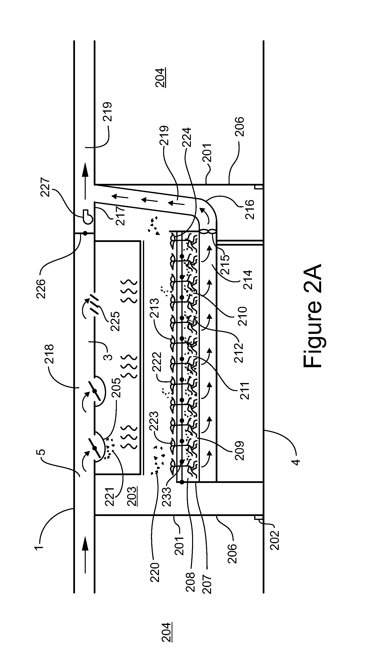
[0214]the invention increases humidity by having the furnace, heating coil or cooling coil of the HVAC upstream of the plant air purifier enclosure.

fourth embodiment

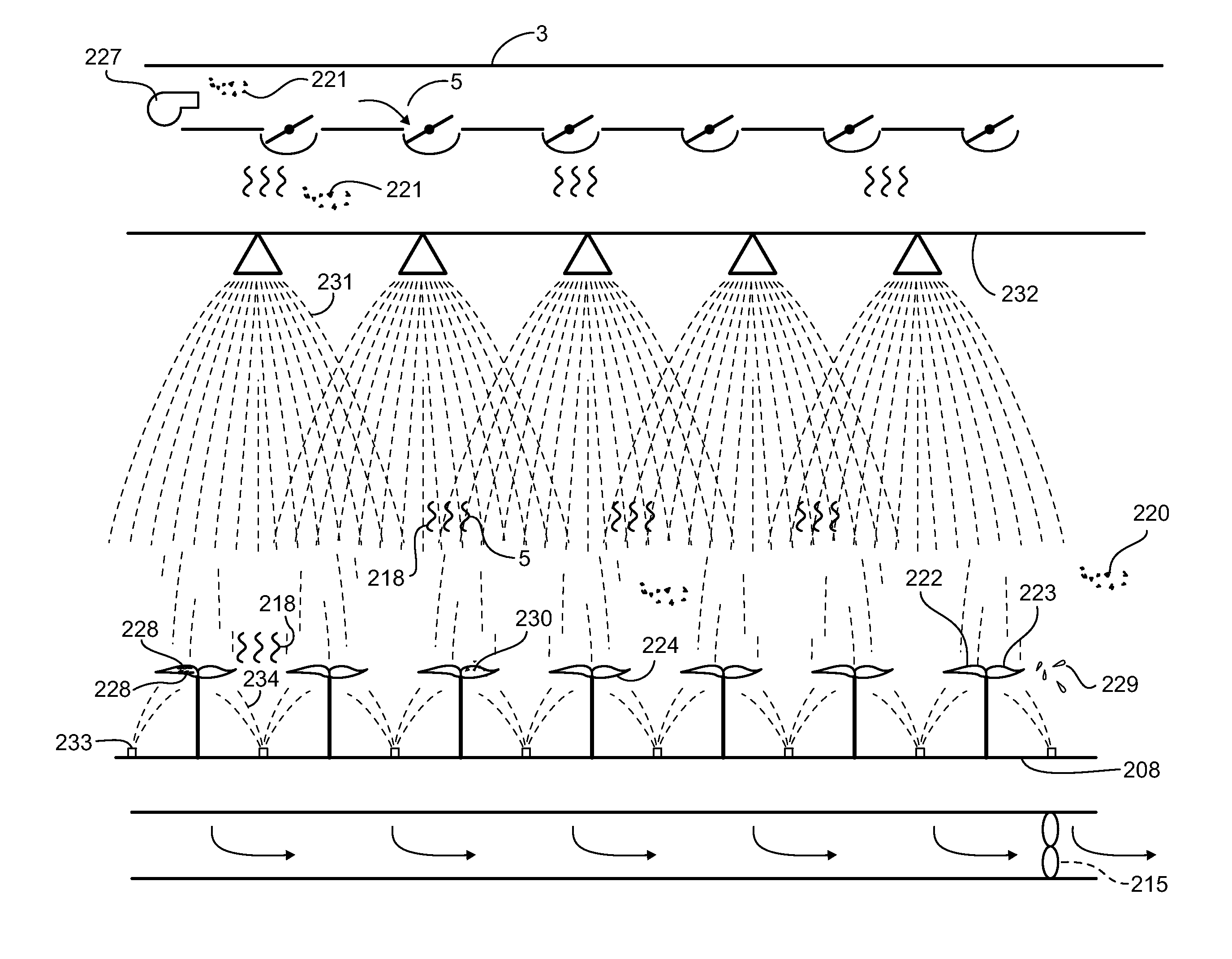
[0215]Lastly the invention increases humidity by increasing the percentage of overall air going through the filter bed.

[0216]Tests conducted at Syracuse University in 2008 at the Center of Excellence which were funded both by NYSERDA and the EPA found that when air was passed through a plant air purifier, the amount of relative humidity increases by 15.8%. However since only 1 / 14 of the total air supply passed through the filter bed the total increase in overall relative humidity for the building's total air supply came to only 1.82%. To increase humidity in the air in the conditioned space all that is necessary is to increase the percentage of overall air going through the filter bed, or to have the furnace, or heating coil and the cooling coil of the HVAC stationed upstream of the plant air purifier enclosure.

[0217]A second method is simply to place the plant air purification enclosure upstream of a location where the air coming out of the enclosure will be cooled either by a dehu...


PUM


Abstract

A plant air purifying enclosure, or “PAPE,” contained within an unconditioned space, either within or outside a building, containing therein a plant air purifier, which is used to purify air using plants and microbes growing therein. The PAPE enclosure itself receives poor indoor quality air from within structure where the PAPE is located or from a structure close by along with thermal energy which keeps the plant air purifier enclosure at a suitable temperature for the plants and air cleaning microbes within the air purifier. Poor air enters the enclosure, is purified by the plants and microbes, and returns in purified form back to the habitable space from which it was taken. This lowers the amount of outside air needed for ventilation purposes and so lessens a building's overall energy consumption while providing efficiently for naturally purified air. Fundamentally, the object of this invention is to specify devices, systems and methods to house / enclose plant purifiers in such a way that they can readily be deployed on a wide scale.

Description

BACKGROUND OF THE INVENTION[0001]For millions of years plants have been cleaning the air, taking in airborne toxins through their stomata, breaking some of these toxins down and transporting the rest down to their roots where they excrete them, whereupon microbes that congregate close by a plant's root system, digest them and transform them into a food source for higher forms of life. For thousands of years humans have taken plants into their homes and unwittingly purified indoor air. Yet it has only been since the early nineteen eighties that plants have purposely been grown in an artificial soil, where air movement mechanisms pull poor indoor quality air directly down into that soil, and where air purifying microbes within that soil break down the impurities contained within indoor air and more efficiently, thereby purify a building's air supply. Such science, much of it developed by NASA, has eliminated the need for plants to act as a transport mechanism of impure air and as a re...

Claims


Application Information

Patent Timeline
Patent Type & Authority Applications(United States)
IPC IPC(8): B01D53/84A01G25/00A01G1/00A01G9/18B08B3/02F21V9/00F24F8/175F24F8/22
CPCB01D53/84F24F2003/1653F24F3/16B01D2259/4508Y02A50/20F24F8/175F24F8/22
Inventor MITTELMARK, MARTIN
Owner MITTELMARK MARC A MR
Why Eureka
Try Eureka