Wireless power transmission apparatus and system

a power transmission apparatus and wireless technology, applied in the direction of safety/protection circuits, inductances, battery overcharge protection, etc., can solve the problems of limited use and mobility of information communication devices, limited power transmission efficiency, and limited wireless information network environmen

Inactive Publication Date: 2012-12-13
SAMSUNG ELECTRONICS CO LTD
View PDF4 Cites 35 Cited by
  • Summary
  • Abstract
  • Description
  • Claims
  • Application Information

AI Technical Summary

Benefits of technology

[0021]The at least one wireless power receiver may include a receiving resonator that includes a capacitor and an inductor, and receives a wireless power signal by magnetic resonance coupling to the wireless power transmitter; a receiving load modulator for performing load modulation communication to perform peer-to-peer wireless communication with the master wireless power receiver; and a power signal converter for maintaining the received wireless power signal at an Alternating Current (AC) signal or converting the received wireless power signal into a Direct Current (DC) signal to charge or supply power to a power consumption device.

Problems solved by technology

Continued use and mobility of the information communication devices are limited because the wired power code or the outlet is needed to recharge the battery.
Therefore, wireless information network environment may not guarantee the true freedom unless the power-related problems of the information communication devices are solved.
The radio wave receiving technology may transmit power over long distances by radiating radio waves into the air via an antenna, but it has a limit on power transmission efficiency due to the very large radiation loss occurring in the air.
The magnetic induction technology, technology based on magnetic energy coupling by a transmitting primary coil and a receiving secondary coil, has high power transmission efficiency, but for power transmission, the transmitting primary coil and the receiving secondary coil should be adjacent to each other within a short distance of about several mm, the power transmission efficiency may dramatically vary depending on coil alignment between the transmitting primary coil and the receiving secondary coil, and heat generation is severe.

Method used


Image

  • Wireless power transmission apparatus and system
  • Wireless power transmission apparatus and system
  • Wireless power transmission apparatus and system

Examples


Embodiment Construction

[0035]The objectives, specific advantages and novel features of the present invention will be more apparatus from the following detailed description taken in conjunction with the accompanying drawings, and preferred embodiments of the present invention. It should be noted that in this specification, the same elements are denoted by the same reference numerals even though they are shown in different drawings. In addition, descriptions of well-known functions and constructions are omitted for clarity and conciseness.

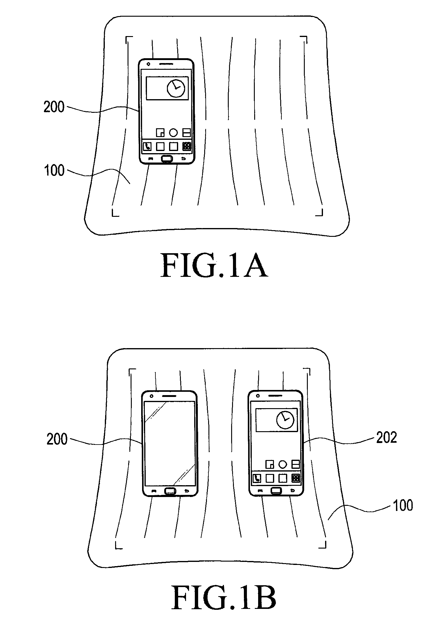
[0036]FIGS. 1A and 1B show an example of a general wireless power transmission system.

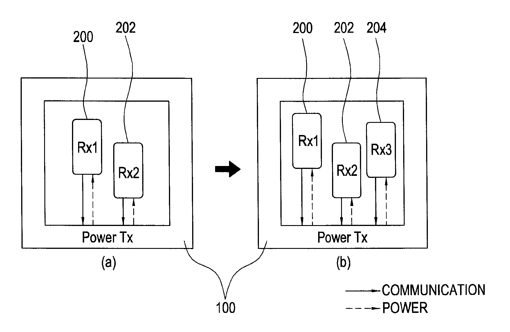
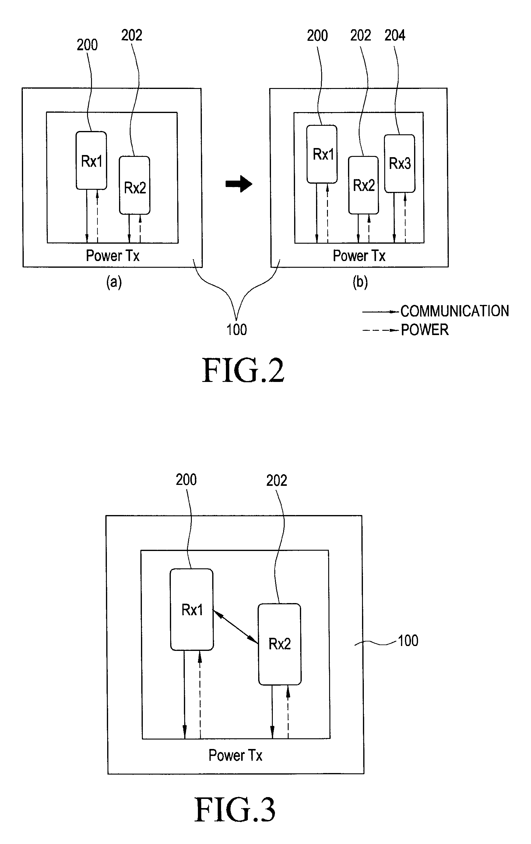
[0037]Referring to FIGS. 1A and 1B, the wireless power transmission system may include a wireless power transmitter Power_Tx and at least one wireless power receivers Rx1 and Rx2. In other words, power may be wirelessly transmitted from a wireless power transmitter 100 to at least one wireless power receiver 200 (FIG. 1A), and power may be wirelessly transmitted from the wireless power tr...


PUM


Abstract

A wireless power transmission apparatus includes a wireless power transmitter for wirelessly transmitting power to at least one wireless power receiver by magnetic resonance coupling; and a master wireless power receiver that is wire-connected to the wireless power transmitter for communication, and performs peer-to-peer wireless communication with the at least one wireless power receiver. A resonant frequency used for the peer-to-peer wireless communication between the master wireless power receiver and the at least one wireless power receiver is identical to a resonant frequency used for the wireless power transmission between the wireless power transmitter and the at least one wireless power receiver.

Description

PRIORITY[0001]This patent application claims priority under 35 U.S.C. §119(e) to patent application filed in the Korean Intellectual Property Office on Jun. 7, 2011 and assigned Serial No. 10-2011-0054804, and Jun. 4, 2012 and assigned Serial No. 10-2012-0059667, the contents of which are incorporated herein by reference.BACKGROUND OF THE INVENTION[0002]1. Field of the Invention[0003]The present invention relates to wireless power transmission apparatus and system. More particularly, the present invention relates to communication between a wireless power transmitter and a wireless power receiver in a wireless power transmission apparatus and system.[0004]2. Description of the Related Art[0005]The development of wireless communication technologies has triggered the advent of ubiquitous information environment in which anyone can exchange all the information they want without the constraints of time and space. Even now, however, for information communication devices, power for their o...

Claims


Application Information

Patent Timeline
Patent Type & Authority Applications(United States)
IPC IPC(8): H02J17/00
CPCH02J5/005H04B5/0081H04B5/0037H02J7/025H02J7/00304H02J7/00302H02J50/80H02J50/12H02J50/40H04B5/0075
Inventor PARK, SE-HOPARK, SUNG-BUMLEE, YOUNG-MIN
Owner SAMSUNG ELECTRONICS CO LTD
Why Eureka
Try Eureka