LED Bulb Structure

a technology of led bulbs and structures, applied in semiconductor devices, light sources, lighting and heating apparatus, etc., can solve the problems of user burnout, slow dissipation, and affecting the work performance of led bulbs

Active Publication Date: 2012-12-13
LEXTAR ELECTRONICS CORP
View PDF5 Cites 11 Cited by
  • Summary
  • Abstract
  • Description
  • Claims
  • Application Information

AI Technical Summary

Problems solved by technology

The surrounding air can only conducts heat exchange on the surface of the heat-dissipation seat, and thus the heat-dissipation is slow and the efficiency thereof is limited, further affecting the work performance of the LED bulb.
As such, the heat-dissipation seat is not pleasing to the eye, and the high temperature of the heat-dissipation is likely to burn a user and also causes safety concerns.

Method used


Image

  • LED Bulb Structure
  • LED Bulb Structure
  • LED Bulb Structure

Examples


Embodiment Construction

[0012]In the following detailed description, for purposes of explanation, numerous specific details are set forth in order to provide a thorough understanding of the disclosed embodiments. It will be apparent, however, that one or more embodiments may be practiced without these specific details. In other instances, well-known structures and devices are schematically depicted in order to simplify the drawings.

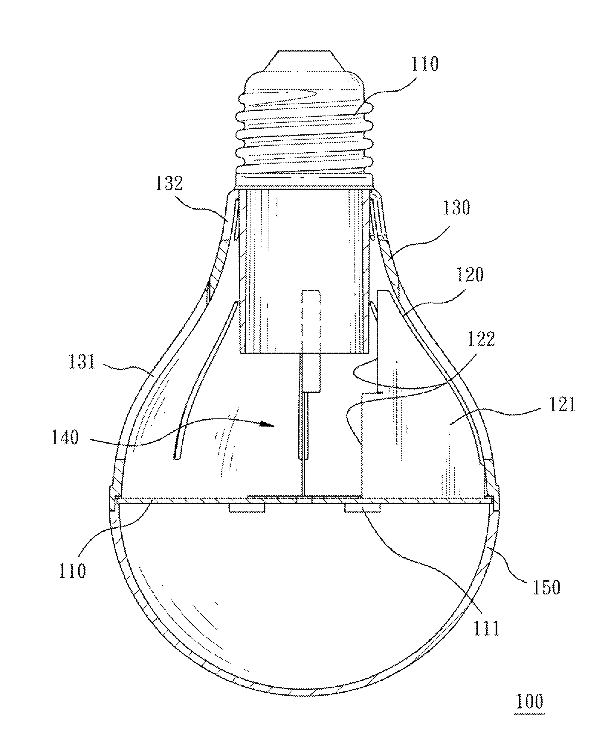
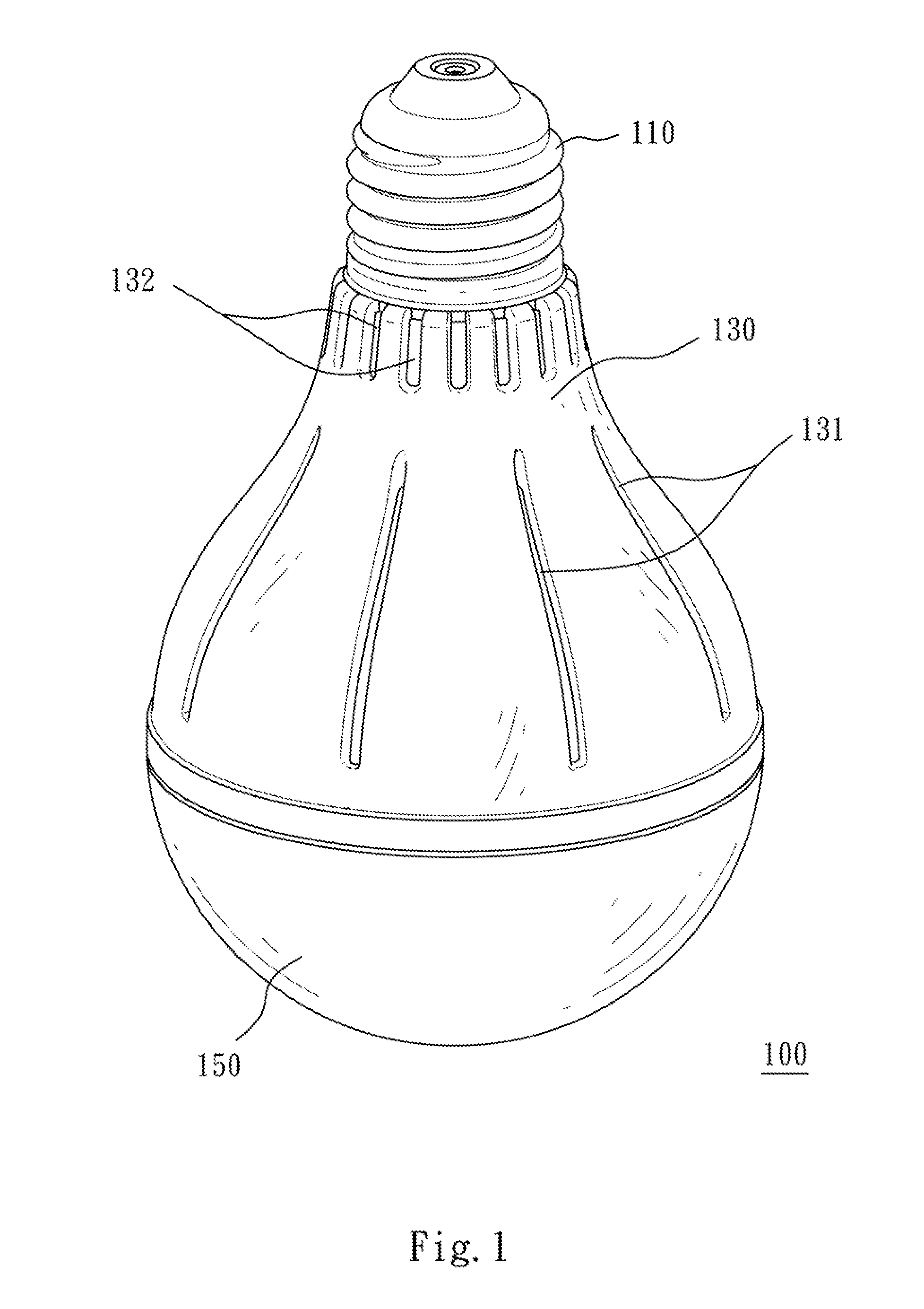
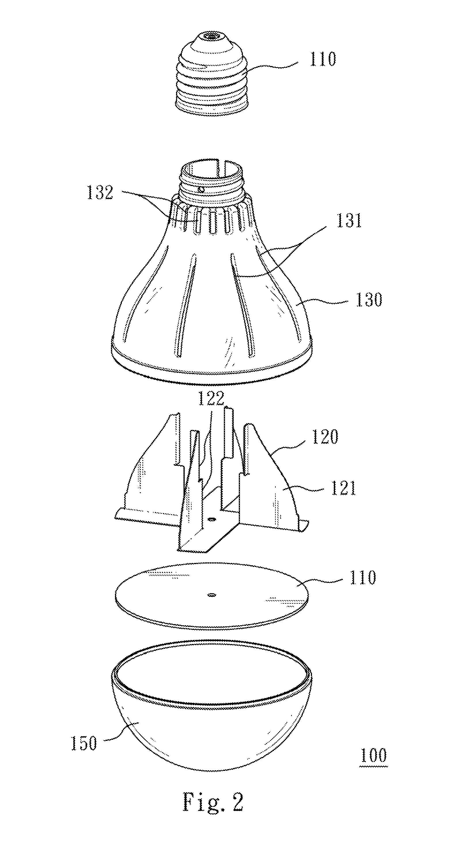
[0013]FIG. 1 is a three dimensional view of a LED bulb structure according to one embodiment. FIG. 2 is an exploded view of the LED bulb structure shown in FIG. 1. FIG. 3 is a cross-sectional of the LED bulb structure shown in FIG. 1. As shown in FIG. 1 to FIG. 3, a LED (Light Emitting Diode) bulb structure 100 includes a base 110, a plurality of fins 120 and a shell 130. This present embodiment uses the shell 130 to enclose the fins 120 for solving the problems of appearance and safety.

[0014]One end of the base 110 is electrically connected to a power source, and the other end ...


PUM


Abstract

A LED (Light Emitting Diode) bulb structure includes a base, a plurality of fins and a shell. One end of the base is electrically connected to a power source, and the other end of the base is used for holding a LED light source. The fins are disposed on a surface of the base. The shell encloses the fins, and the shell includes a plurality of first heat-dissipation holes and a plurality of second heat-dissipation holes. The first heat-dissipation holes are arranged around the shell and corresponding to the fins for allowing airflow entering the first heat-dissipation holes to directly pass through each of the fins corresponding to each of the first heat-dissipation holes. The second heat-dissipation holes are arranged around the shell and disposed above the first heat-dissipation holes for enabling the first heat-dissipation holes and the second heat-dissipation holes to conduct thermal convection.

Description

RELATED APPLICATIONS[0001]The application claims priority to Taiwan Application Serial Number 100210394, filed Jun. 8, 2011, which is herein incorporated by reference.BACKGROUND[0002]1. Technical Field[0003]The present invention relates to a lighting device. More particularly, the present invention relates to a light bulb device.[0004]2. Description of Related Art[0005]A conventional light bulb uses tungsten as a light-emitting source, and has a simple structure and can be mounted and replaced conveniently. The tungsten light bulb structure generally has a spherical light cover of which a tail end is fixed to an adapter, wherein the adapter can be threaded into a normal bulb seat. When power is turned on, the tungsten inside the light cover will generate heat and emit light to achieve illumination purpose.[0006]In recent years, since having the features such as small volume, low driving voltage, rapid response rate, aseismatic, long-lifted and environmentally friendly, a LED (Light-...

Claims


Application Information

Patent Timeline
Patent Type & Authority Applications(United States)
IPC IPC(8): F21V3/00F21V29/00
CPCF21V29/83F21K9/135F21K9/232
Inventor CHEN, KUO-CHIANG
Owner LEXTAR ELECTRONICS CORP
Why Eureka
Try Eureka