Synchronous ac rectified flyback converter utilizing boost inductor

a technology of synchronous ac and inductance, applied in the direction of electric variable regulation, process and machine control, instruments, etc., can solve the problems of harmonics traveling, load impedance to the ac mains, and most power supplies,

Inactive Publication Date: 2012-12-13
COMARCO WIRELESS SYST LLC
View PDF4 Cites 26 Cited by
  • Summary
  • Abstract
  • Description
  • Claims
  • Application Information

AI Technical Summary

Problems solved by technology

Most power supplies, however, present a non-linear, rather than a linear, load impedance to the AC mains.
High harmonic content in the current waveform not only lowers the power factor, the harmonics may travel down the neutral line of the AC mains and disrupt other devices connected thereto.
However, due to component size constraints, power factor correction circuits which use active circuits are more common.
Such an arrangement increases component count and associated cost.
Use of a diode bridge rectifier causes conduction loss.
This results in continuous conduction losses which decrease the efficiency of the power converter.
The conduction losses also cause the undesirable generation of heat.

Method used


Image

  • Synchronous ac rectified flyback converter utilizing boost inductor
  • Synchronous ac rectified flyback converter utilizing boost inductor
  • Synchronous ac rectified flyback converter utilizing boost inductor

Examples


Embodiment Construction

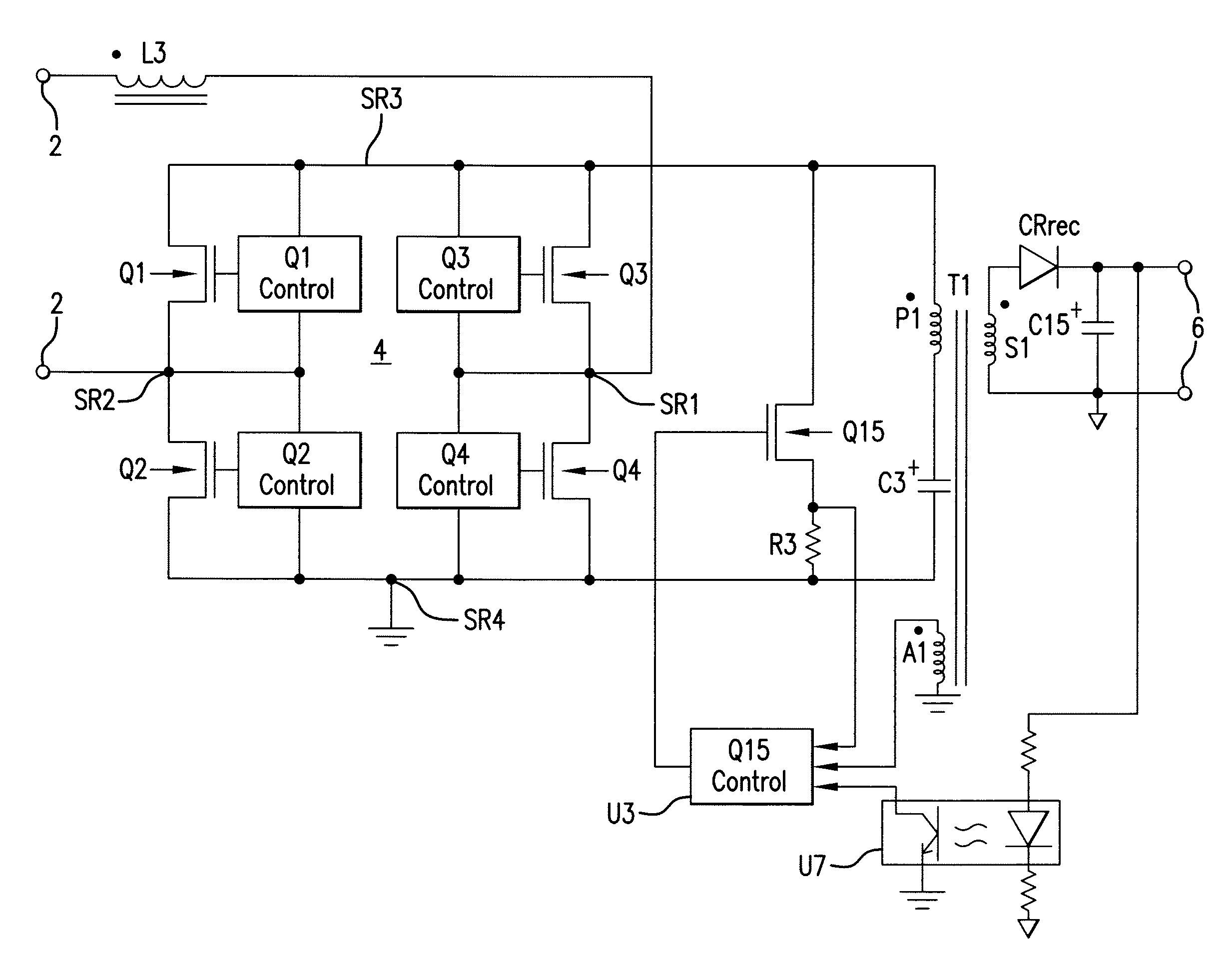
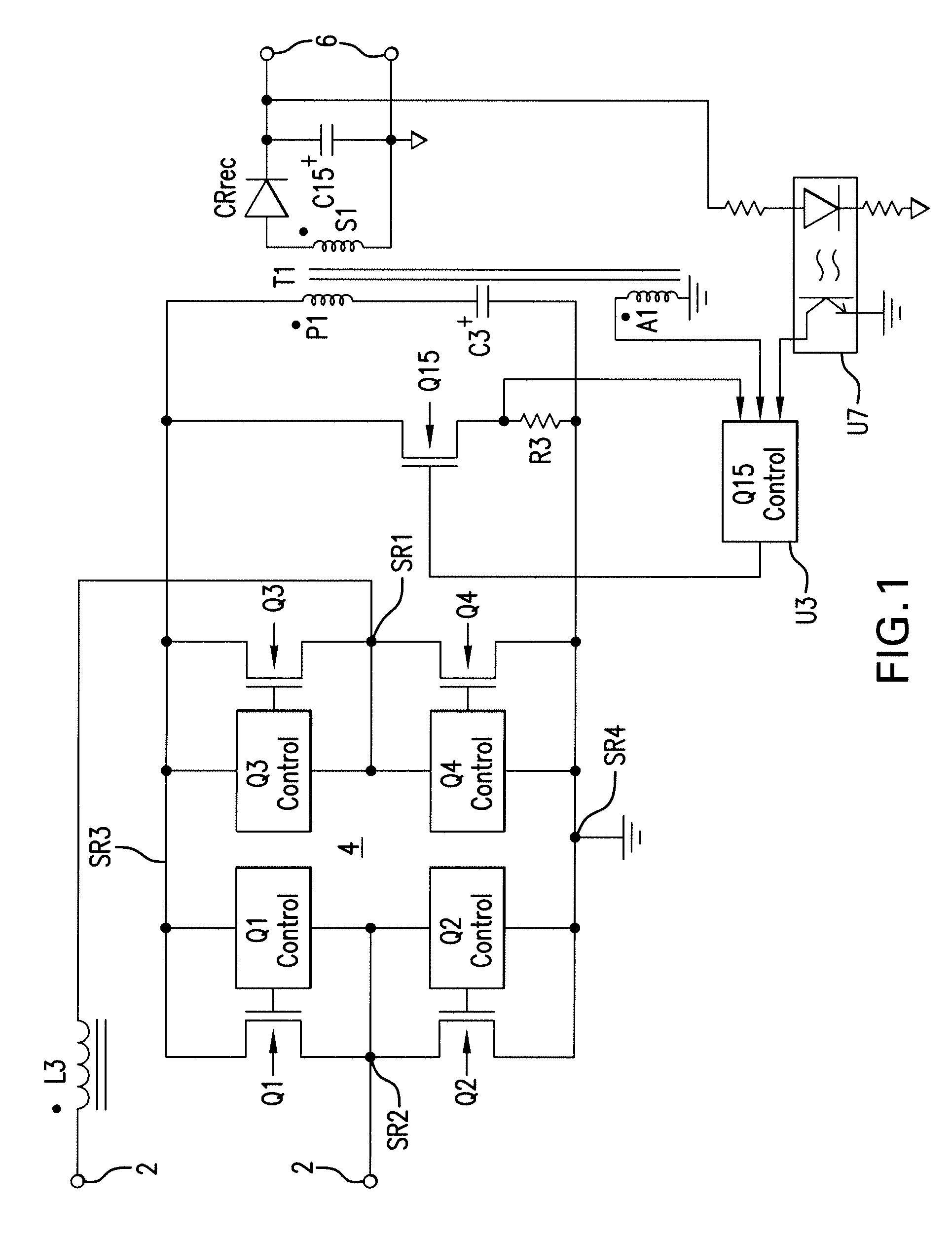
[0025]Referring to FIG. 1, there is shown a combination block diagram / schematic diagram which illustrates a configuration of the invention. A pair of input terminals 2 receives a source of AC power. The applied AC voltage may be 120 VAC at 60 Hz, 240 VAC at 50 Hz or some other values of line voltage and line frequency.

[0026]A boost inductor L3 is coupled at one end of its winding to one of the input terminals 2 and at the other end of its winding to an input SR1 of a synchronous rectifier 4. The winding is wound around a magnetic core. The synchronous rectifier 4 is comprised of transistors Q1-Q4 and associated control circuits to provide full wave rectification of the AC input voltage. As explained below, the synchronous rectifier also periodically passes current resulting from the release of energy stored in the magnetic core of the boost inductor L3. The second input SR2 of the synchronous rectifier 4 is coupled to the second of the input terminals 2.

[0027]In the illustrated embo...


PUM


Abstract

A flyback converter utilizes a boost inductor coupled between a source of AC power and a synchronous rectifier to provide power factor correction. The synchronous rectifier includes four field-effect transistors configured in a bridge arrangement. Control circuitry controls the on / off states of opposite pairs of the FETs to provide synchronous rectification of the AC power. A primary winding of the flyback transformer is coupled in series with a storage capacitor across the output of the synchronous rectifier. A circuit, which includes a switching transistor, is also coupled across the output of the synchronous rectifier to provide a low resistance path when the switch is closed. The cores of the boost inductor and the transformer are loaded with energy when the switch is closed. When the switch opens, the energy stored in the magnetic cores is transferred to the output via the transformer secondary winding and rectification circuitry. In one embodiment, a separate switching transistor is not used and its function is performed by the rectifier FETs.

Description

RELATED APPLICATION[0001]This application is in the same technical field as U.S. patent application Ser. No. 12 / 646,152, filed Dec. 23, 2009, the disclosure of which is incorporated herein by reference.FIELD OF THE INVENTION[0002]The present invention relates to power supplies, also known as power adapters and power converters. In particular, the invention concerns a flyback converter which utilizes a boost inductor coupled between a source of AC power and a synchronous rectifier to provide power factor correction and low conduction loss associated with rectification.BACKGROUND OF THE INVENTION[0003]Power factor is the ratio of real power to apparent power. Real power is the average (over a cycle) of the instantaneous product of current and voltage. Apparent power is the product of the RMS value of current times the RMS value of voltage. Real power is the power required to do the needed work. Apparent power is the power that is supplied by the electricity generator (e.g., a power co...

Claims


Application Information

Patent Timeline
Patent Type & Authority Applications(United States)
IPC IPC(8): H02M3/335
CPCH02M1/4258Y02B70/1408Y02B70/126H02M2007/2195H02M7/2195Y02B70/10
Inventor LANNI, THOMAS W.
Owner COMARCO WIRELESS SYST LLC
Why Eureka
Try Eureka