Serviceable snap-in fastener

a technology of snap-in fasteners and snap-in fasteners, which is applied in the direction of snap-in fasteners, buckles, manufacturing tools, etc., can solve the problems of inability to provide a mechanism for separating panels, parts of the fastener being separated before the panels are damaged, and the initial formation process is complex

Active Publication Date: 2012-12-20
ILLINOIS TOOL WORKS INC
View PDF2 Cites 17 Cited by
  • Summary
  • Abstract
  • Description
  • Claims
  • Application Information

AI Technical Summary

Problems solved by technology

Such unitary constructions have performed well and have the benefit of being formed in a single molding operation but they do not provide a mechanism to separate the panels after the connection has been made.
That is, the portions of the fastener separate before the panels are damaged.
While such multi-piece structures perform well, there is a degree of inherent complexity in the initial formation process since two different parts must be formed.

Method used


Image

  • Serviceable snap-in fastener
  • Serviceable snap-in fastener
  • Serviceable snap-in fastener

Examples


Embodiment Construction

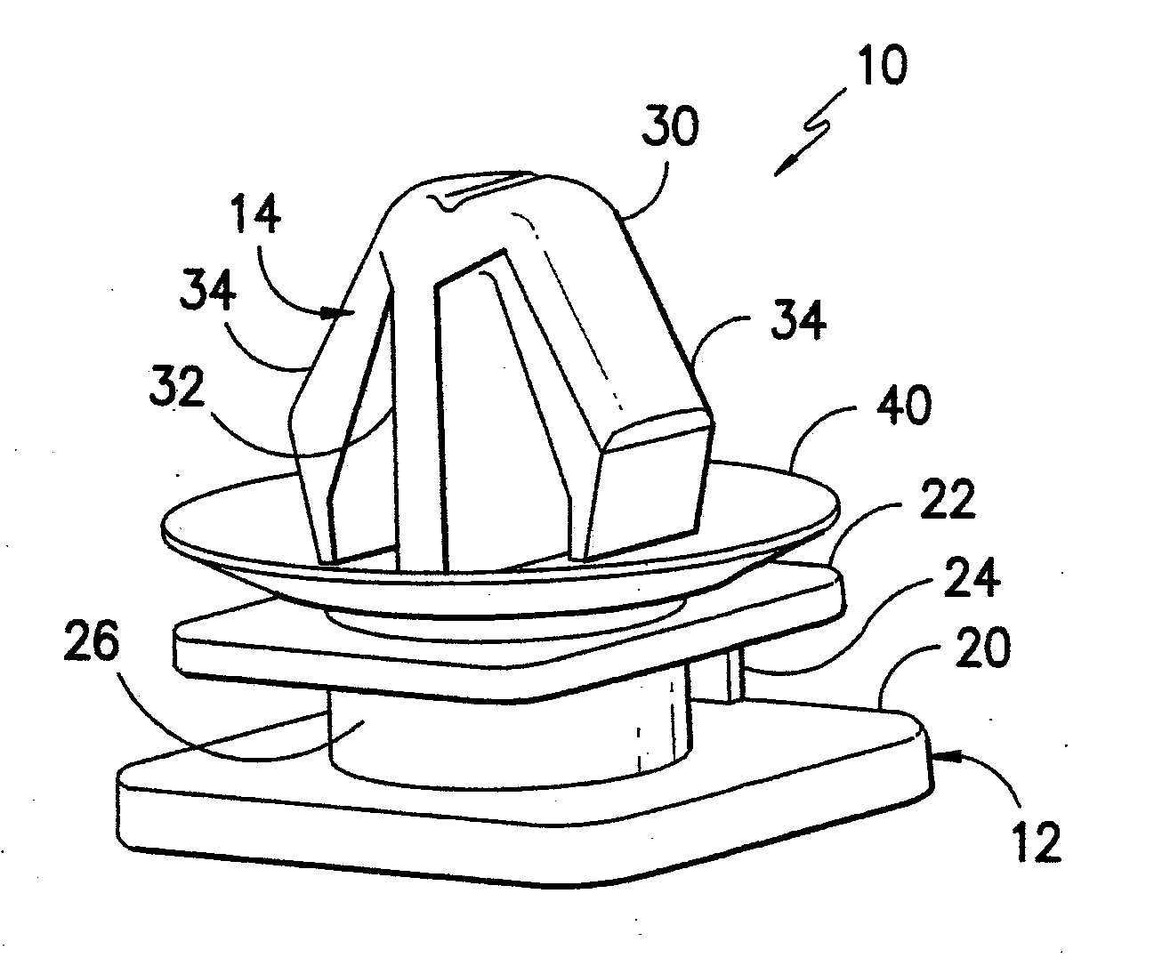
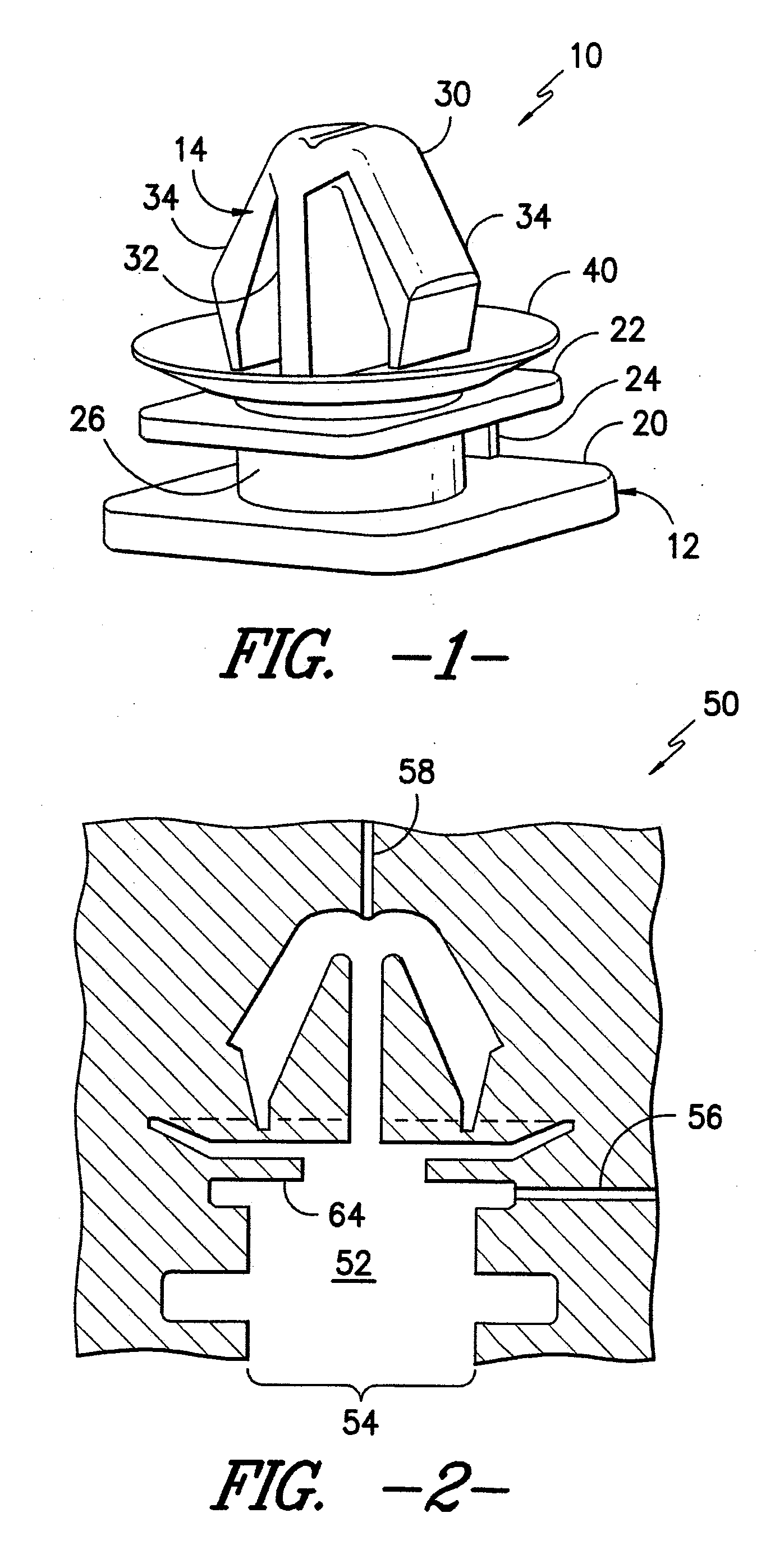
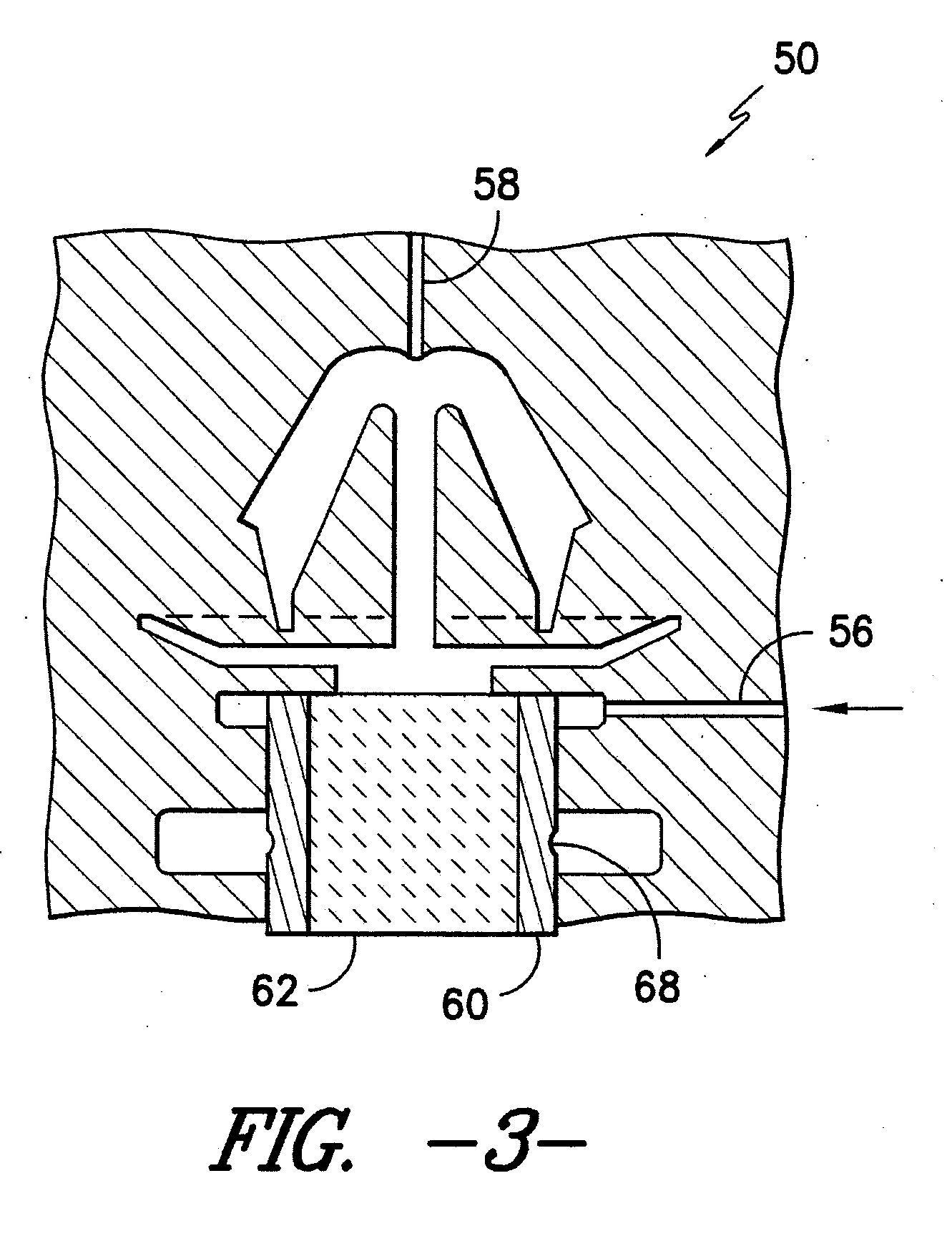
[0015]Reference will now be made to the drawings wherein to the extent possible, like elements are designated by like reference numerals in the various views. As shown in FIG. 1, an exemplary snap-in fastener 10 also referred to as a “retainer”) includes a head portion 12 and a base clip portion 14 projecting outwardly away from the head portion 12. As best seen in FIGS. 5 and 6, during use the base clip portion 14 is held in locked relation within an opening in a primary structure 16 such as a structural panel of sheet metal, plastic or the like. The head portion 12 is adapted to be held at a secondary structure 18 such as a doghouse connector or slot opening in a piece of trim or the like in a manner as will be well known to those of skill in the art. Thus, the primary structure 6 and the secondary structure 18 are held in a fixed juxtaposed relation.

[0016]As seen in FIG. 1, in the illustrated exemplary construction, the head portion 12 includes a first circumferential flange 20 i...


PUM

PropertyMeasurementUnit
axial tensioning forceaaaaaaaaaa
melting pointaaaaaaaaaa
lengthaaaaaaaaaa

Abstract

A one piece snap-in retainer of multi-shot molded construction adapted to separate along a molded-in fracture line upon application of axial tensioning force. The retainer includes a base clip portion of molded polymer with a proximal barrel segment and a distal snap-in element projecting outwardly away from the barrel segment. The retainer also includes a head portion of molded polymer at least partially surrounding the proximal barrel segment. The molded-in fracture line includes a protuberance molded into the proximal barrel segment or the head portion at the interface in combination with an opposing complimentary mating depression molded into the other of the proximal barrel segment or the head portion.

Description

CROSS-REFERENCE TO RELATED APPLICATION[0001]This non-provisional application claims the benefit of, and priority from, U.S. Provisional Application 61 / 316,888 filed Mar. 24, 2010 the contents of which are hereby incorporated by reference in their entirety as if fully set forth herein.TECHNICAL FIELD[0002]The present invention relates generally to fastening structures, and more particularly to snap-in fasteners (also referred to as retainers) adapted to connect a panel or the like in opposing relation to another structure. More particularly, the present invention relates to snap-in fasteners formed by multi-shot molding such that a unitary structure is provided with different portions formed during different molding shots such that portions may be separated from one another along pre-defined interfaces if desired.BACKGROUND OF THE INVENTION[0003]It is known to use snap-in fasteners to connect panels or other structures in opposing relation to one another. A number of prior component ...

Claims


Application Information

Patent Timeline
Patent Type & Authority Applications(United States)
IPC IPC(8): F16B13/02B29C45/16
CPCB29C45/1635Y10T24/44026B29L2031/7282
Inventor RISDALE, MARC R.MURAWSKI, ROBERT A.
Owner ILLINOIS TOOL WORKS INC
Why Eureka
Try Eureka