
Tire vulcanizer and tire vulcanizing method

a technology of vulcanizer and tire, which is applied in the direction of tyres, domestic applications, belts, etc., can solve the problems of uneconomically provided two same systems, and achieve the effect of improving economic efficiency

Inactive Publication Date: 2012-12-20
KOBE STEEL LTD
View PDF2 Cites 6 Cited by
  • Summary
  • Abstract
  • Description
  • Claims
  • Application Information

AI Technical Summary

Benefits of technology

[0009]An object of the present invention is to provide a tire vulcanizer capable of improving economical efficiency in a twin type tire vulcanizer, and a tire vulcanizing method.
[0011]According to the above configuration, the vulcanization gas heated in the first heating device is supplied to the interior of the bladder of the center mechanism which is placed on the upstream side in the circulating direction of the vulcanization gas. Thereby, the vulcanization and the patterning of the green tire are performed in the upper and lower molds placed on the upstream side in the circulating direction of the vulcanization gas. The vulcanization gas discharged from the interior of the bladder of the center mechanism which is placed on the upstream side in the circulating direction of the vulcanization gas is used for the vulcanization and the patterning, so that a temperature thereof is lowered. However, this vulcanization gas is heated again in the second heating device, so that the temperature is increased. Therefore, the vulcanization gas heated in the second heating device is supplied to the interior of the bladder of the center mechanism which is placed on the downstream side in the circulating direction of the vulcanization gas. Thereby, the vulcanization and the patterning of the green tire are performed in the upper and lower molds placed on the downstream side in the circulating direction of the vulcanization gas. The vulcanization gas discharged from the interior of the bladder of the center mechanism which is placed on the downstream side in the circulating direction of the vulcanization gas is used for the vulcanization and the patterning, so that the temperature thereof is lowered. However, this vulcanization gas is heated again in the first heating device, so that the temperature is increased. In such a way, the vulcanization and the patterning are respectively performed in the two sets of upper and lower molds. In this manner, even when systems for circulating the vulcanization gas are not respectively provided for the center mechanisms, two green tires can be respectively vulcanized and patterned with one system shared by the two center mechanisms. Therefore, the economical efficiency can be improved.
[0013]According to the above configuration, since the vulcanization gas is generally exhausted through the medium exhausting passages after completion of the vulcanization, thermal energy and pressure energy remaining in the tire vulcanizer are released to the exterior of the tire vulcanizer at the time of the completion of the vulcanization, so that energy efficiency is unfavorable. Thus, the vulcanization gas discharged from the interiors of the bladders is stored in the interior of the tank. The vulcanization gas stored in the interior of the tank is supplied to the interiors of the bladders at the time of the shaping. In general, the bladders are extended with a low-pressure gas supplied from a low-pressure gas supply source at the time of the shaping. However, the bladders are extended with the vulcanization gas stored in the interior of the tank instead of the low-pressure gas. In such a way, by extending the bladders with the vulcanization gas stored in the interior of the tank, the thermal energy and the pressure energy remaining in the tire vulcanizer can be reused, and a supply amount of the low-pressure gas supplied from the low-pressure gas supply source can be decreased. The vulcanization gas stored in the interior of the tank is supplied to the interiors of the bladders at the beginning of the vulcanization and the patterning. In general, the vulcanization and the patterning are performed with a high-temperature and high-pressure vulcanization gas circulated in the medium circulating passage. However, since pressure of the vulcanization gas is lowered at the beginning of the vulcanization and the patterning, there is a need for supplementing a high-pressure vulcanization gas from a vulcanization gas supply source and heating the supplemented vulcanization gas. In this regard, by using the vulcanization gas stored in the interior of the tank at the beginning of the vulcanization and the patterning, the thermal energy and the pressure energy remaining in the tire vulcanizer can be reused, and a supply amount of the high-pressure vulcanization gas supplemented from the vulcanization gas supply source can be decreased, so that thermal energy for heating the supplemented vulcanization gas can be decreased. By using the high-temperature vulcanization gas stored in the interior of the tank at the beginning of the vulcanization and the patterning, a temperature of the interiors of the bladders can be promptly increased, so that a vulcanization time can be shortened. Thereby, energy efficiency can be improved.
[0015]According to the tire vulcanizer and the tire vulcanizing method of the present invention, even when systems for circulating the vulcanization gas are not respectively provided for the center mechanisms, two green tires can be respectively vulcanized and patterned with one system shared by the two center mechanisms. Therefore, the economical efficiency can be improved.

Problems solved by technology

Therefore, the two same systems are uneconomically provided.

Method used


Image

  • Tire vulcanizer and tire vulcanizing method
  • Tire vulcanizer and tire vulcanizing method
  • Tire vulcanizer and tire vulcanizing method

Examples


first embodiment

Configuration of Tire Vulcanizer

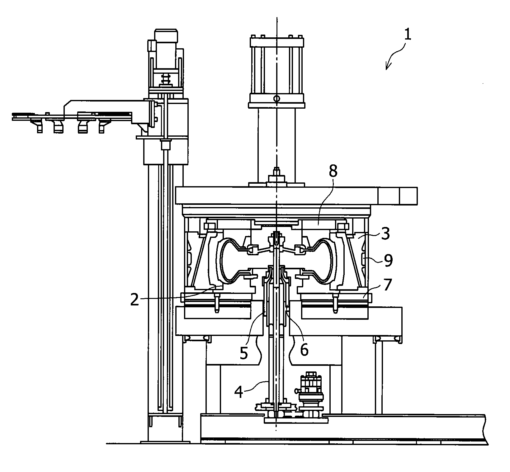
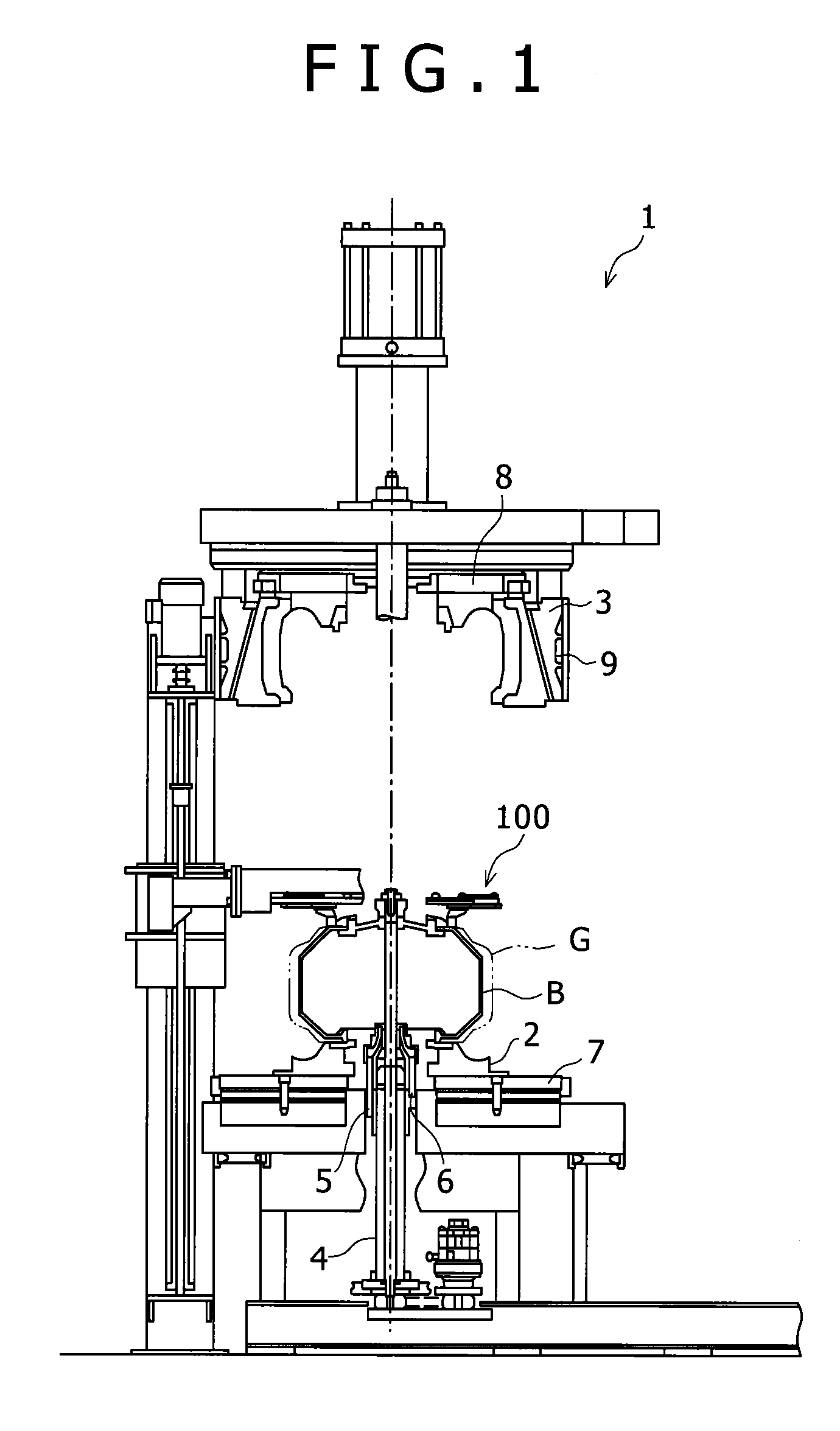
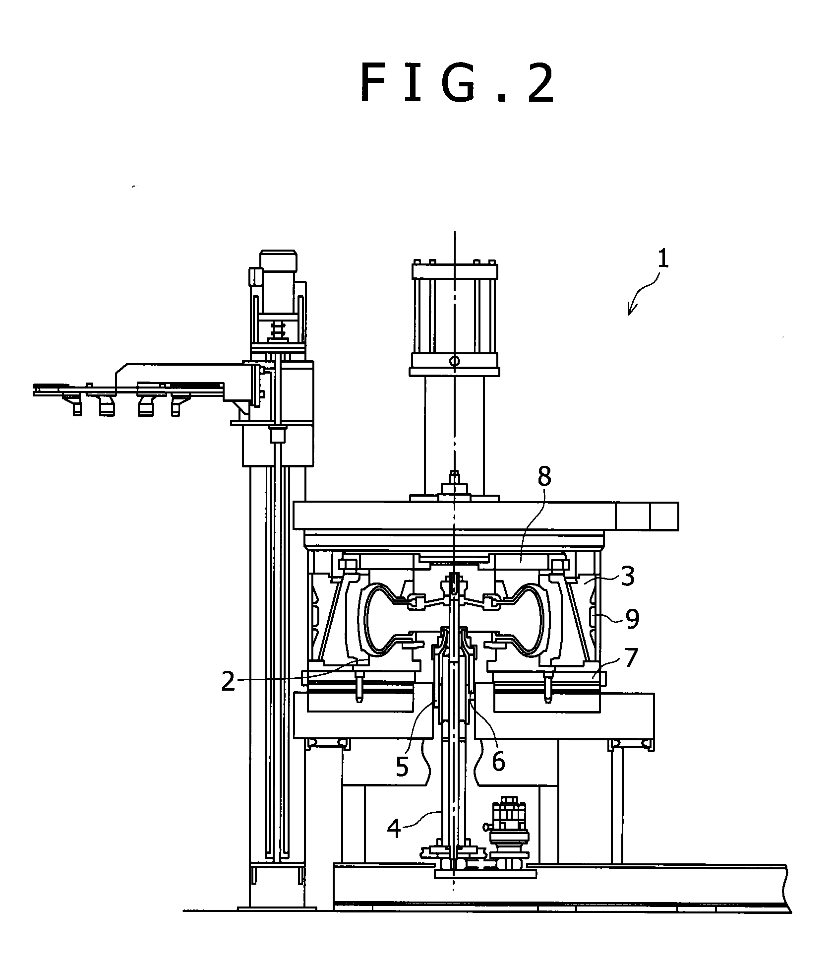
[0021]A tire vulcanizer 1 according to the present embodiment has lower and upper molds 2, 3 in which a green tire G is detachably placed as shown in FIG. 1. The green tire G is patterned and formed by connecting and attaching constituent members such as a bead, a tread, and a side wall to each other in a patterning step. This green tire G is carried to a vulcanization step, and vulcanized and patterned in the tire vulcanizer 1.

[0022]The lower mold 2 is replaceably provided on a lower heat plate 7 serving as a heat source. The upper mold 3 is replaceably provided under an upper heat plate 8 serving as a heat source. A jacket 9 serving as a heat source is provided in a periphery of the upper mold 3. By moving the upper mold 3 upward and downward by an upper structure, the upper mold 3 is openable and closable from the upper side relative to the lower mold 2. As shown in FIG. 1, in a state that the lower mold 2 and the upper mold 3 are opened, the green...

second embodiment

Configuration of Tire Vulcanizer

[0054]Next, a tire vulcanizer 201 according to a second embodiment will be described. It should be noted that the same configurations as the tire vulcanizer 1 according to the first embodiment will be given the same reference numerals, and description thereof will be omitted.

[0055]The tire vulcanizer 201 of the second embodiment is different from the tire vulcanizer 1 of the first embodiment in a point that as shown in FIG. 4, the tire vulcanizer has a tank 70 provided in the medium exhausting passage 57, for storing the nitrogen gas discharged from the interiors of the bladders B, and medium supplying paths 58, 59, 60 respectively provided for the center mechanisms 4L, 4R, for supplying the nitrogen gas in an interior of the tank 70 to the interiors of the bladders B.

[0056]The nitrogen gas discharged from the interiors of the bladders B of the center mechanisms 4L, 4R passes through the medium exhausting passage 56 and the medium exhausting passage 6...


PUM

PropertyMeasurementUnit
pressureaaaaaaaaaa
pressureaaaaaaaaaa
pressureaaaaaaaaaa

Abstract

In a tire vulcanizer having two sets of portions, each of which includes a lower mold, an upper mold, and a center mechanism provided with a bladder, a nitrogen gas heated in a first heating device is supplied to an interior of the bladder of the center mechanism which is placed on the upstream side in the circulating direction of the nitrogen gas. The nitrogen gas discharged from the interior of the bladder of the center mechanism is used for vulcanization and patterning and a temperature thereof is lowered. However, this nitrogen gas is heated again in a second heating device, so that the temperature is increased. Therefore, the nitrogen gas heated in the second heating device is supplied to an interior of the bladder of the center mechanism which is placed on the downstream side in the circulating direction of the nitrogen gas.

Description

BACKGROUND OF THE INVENTION[0001]1. Field of the Invention[0002]The present invention relates to a tire vulcanizer for squeezing upper molds and lower molds so as to vulcanize and pattern green tires, and a tire vulcanizing method.[0003]2. Description of the Related Art[0004]In a manufacturing step of a tire, a green tire made by assembling constituent members of the tire is vulcanized by a tire vulcanizer. A bladder to be inflated by a low-pressure pressure medium is closely attached to an inner circumferential surface of the green tire installed between openable and closable upper and lower molds by a center mechanism of the tire vulcanizer. After that, the green tire is heated from inside by squeezing of the upper and lower molds and introduction of a high-pressure heating medium to an interior of the bladder. The upper and lower molds are always heated by platen, the green tire is vulcanized by heating from an inner surface and an outer surface thereof.[0005]There are various ty...

Claims


Application Information

Patent Timeline
Patent Type & Authority Applications(United States)
IPC IPC(8): B29C35/02B29D30/06
CPCB29D30/0601B29D2030/0651B29D2030/0675B29C35/04B29D30/08
Inventor MIZUTA, YUICHIROFUJIEDA, YASUHIKODOE, MASAHIRO
Owner KOBE STEEL LTD
Learn More