Pedestrian crossing signal system

a pedestrian crossing and signal system technology, applied in the direction of instruments, roads, construction, etc., can solve the problems of pedestrian crossing lines, pedestrians are often not seen by motorists, pedestrian crossings are located on roadway surfaces, etc., and achieves low cost, low cost, and simple design.

Inactive Publication Date: 2012-12-20
KUPCZYN ANDREW S
View PDF7 Cites 5 Cited by
  • Summary
  • Abstract
  • Description
  • Claims
  • Application Information

AI Technical Summary

Benefits of technology

[0005]It is another object of the present invention to provide a pedestrian crossing signal system in which its signaling stations comprise high towers with high powered solar energized strobe lights, to provide clear notice to oncoming traffic of the presence of pedestrians who are crossing from one end of the intersection to the other.
[0006]It is a further object of the present invention to provide a pedestrian crossing signal system which is relative simple in design, has few components, and is thus economical to manufacture and install.
[0007]These and other objects are accomplished by the present invention, a pedestrian crossing signal system comprising two signaling stations, one to be positioned at each end of a crosswalk on a roadway. Each station utilizes a tower of appropriate height, e.g. eight feet, having a high powered signal strobe light mounted at the top of the tower. A push button actuator turns on the strobe light. Electricity for powering the light is derived from a battery mounted within a compartment in the base of the tower. A solar panel provides energy to continually charge the battery. When the actuating button is pushed by a pedestrian, the strobe light is turned on providing immediate and clear notice to oncoming vehicular traffic of the presence of a pedestrian at the end of the crosswalk.

Problems solved by technology

However, crosswalk lines, being located on the roadway surfaces, are often not seen by motorists, especially during dawn, dusk, or nighttime hours.
In fact, motorists sometime fail to observe pedestrians crossing the roadway at all, either because of poor lighting or inattention.
However, these systems are usually located only at major intersections.

Method used


Image

  • Pedestrian crossing signal system
  • Pedestrian crossing signal system
  • Pedestrian crossing signal system

Examples


Embodiment Construction

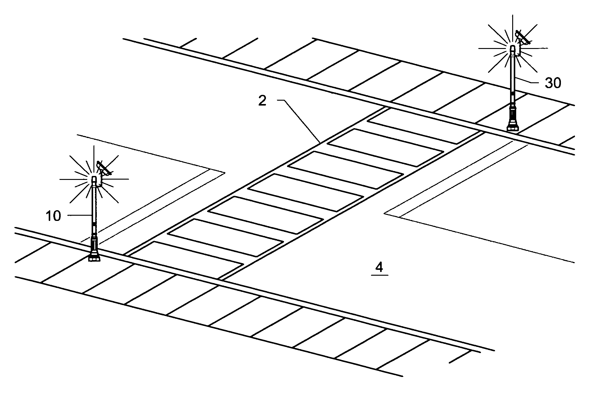
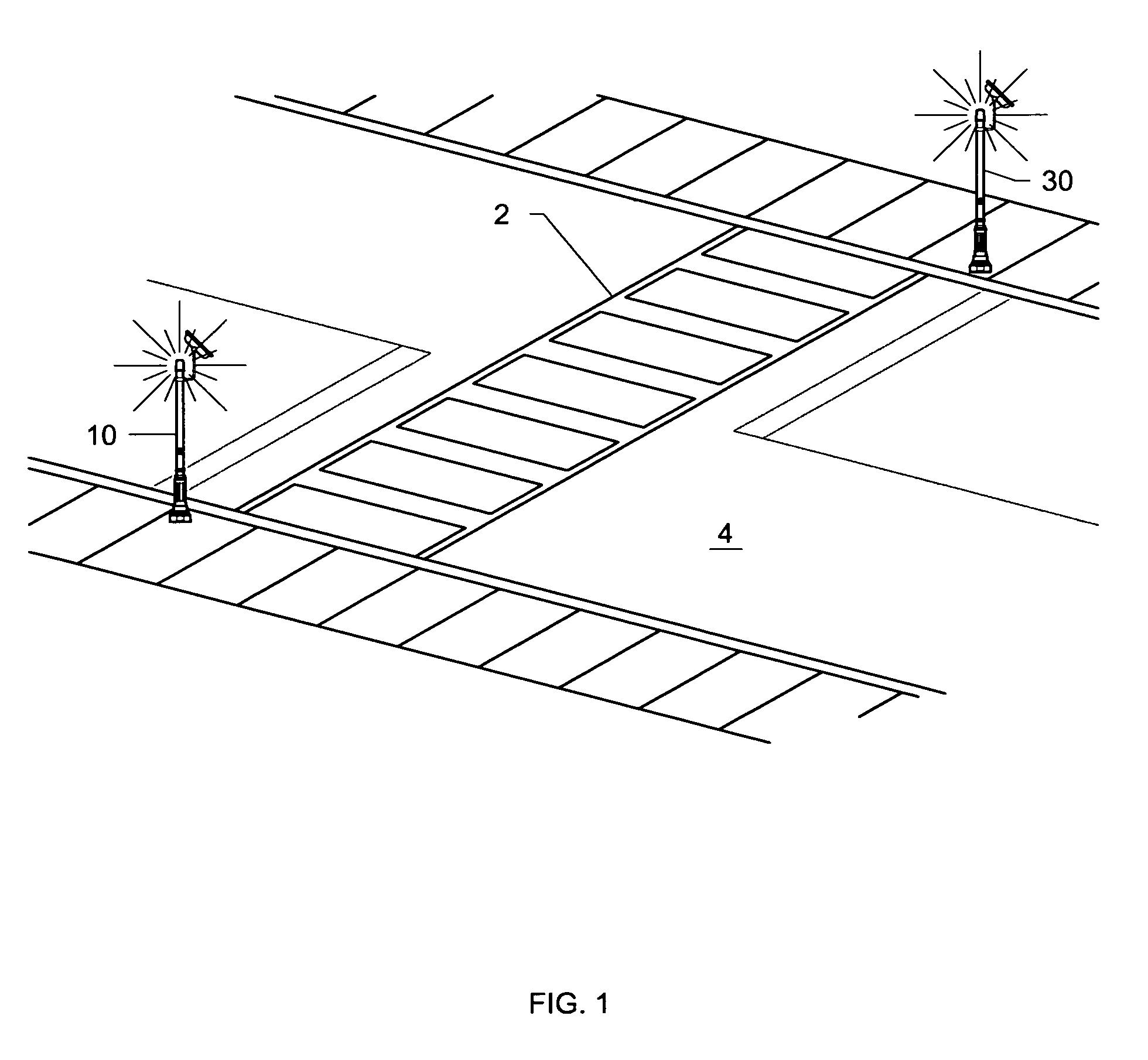
[0013]It is contemplated that the pedestrian crossing signal system of the present invention will be located on vehicular trafficked roads and streets where there are no traffic lights, signs, or other pedestrian assisting aids. The present system provides such an aid by utilizing two signaling stations 10 and 30, positioned at opposite ends of crosswalk 2, located across road surface 4. See FIG. 1.

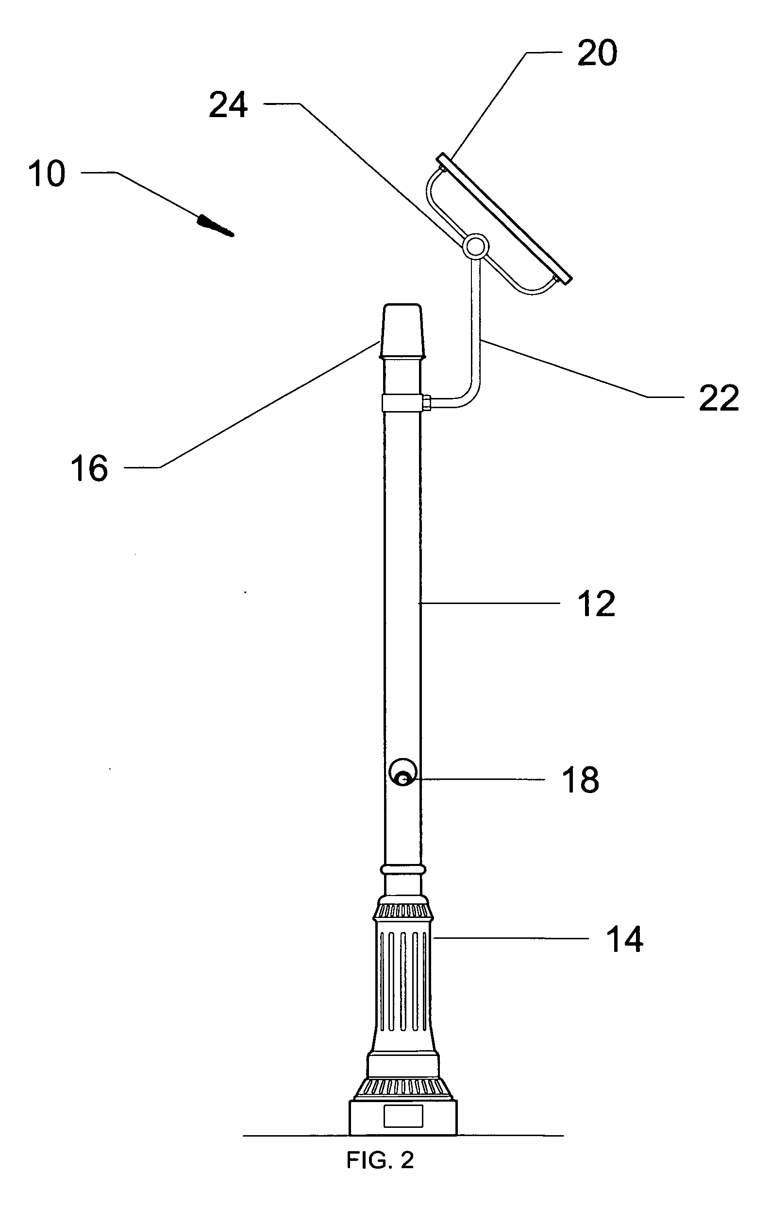
[0014]FIG. 2 shows representative signaling station 10 comprising tower 12. Tower 12 is designed to be high enough to be easily seen by passing motorists, e.g. eight feet in height. The tower is an elongated post made of aluminum or high grade amber plastic. It is noted that the height and construction material of tower 12 are disclosed as examples only, and the invention should not be deemed restricted to these parameters. The tower for signaling station 30 is identical to tower 12.

[0015]Tower 12 comprises base section 14 which maintains the tower at the end of the crosswalk, high powere...


PUM


Abstract

A pedestrian crossing signal system utilizes two signaling stations, one to be positioned at each end of a crosswalk on a roadway. Each station utilizes a tower of appropriate height, e.g. eight feet, having a high powered signal strobe light mounted at the top of the tower. A push button actuator turns on the strobe light. Electricity for powering the light is derived from a battery mounted within a compartment in the base of the tower. A solar panel provides energy to continually charge the battery. When the actuating button is pushed by a pedestrian, the strobe light is turned on providing immediate and clear notice to oncoming vehicular traffic of the presence of a pedestrian at the end of the crosswalk.

Description

BACKGROUND OF THE INVENTION[0001]Pedestrian crosswalks are painted on roadway surfaces both for the safety of pedestrians and to provide notice to motorists of pedestrians in these safety zones. However, crosswalk lines, being located on the roadway surfaces, are often not seen by motorists, especially during dawn, dusk, or nighttime hours. In fact, motorists sometime fail to observe pedestrians crossing the roadway at all, either because of poor lighting or inattention.[0002]This problem is somewhat alleviated by traffic light systems having “Walk / Don't Walk” signals. However, these systems are usually located only at major intersections. A pedestrian desiring to cross a busy street having a crosswalk but no other means to provide notice of the crossing to vehicular traffic, is at the mercy of the inattentive motorist.SUMMARY OF THE INVENTION[0003]It is thus the object of the present invention to provide a pedestrian crossing signal system which squarely addresses the issue of pede...

Claims


Application Information

Patent Timeline
Patent Type & Authority Applications(United States)
IPC IPC(8): G08G1/095
CPCG08G1/005G08G1/095E01F9/615
Inventor KUPCZYN, ANDREW S.
Owner KUPCZYN ANDREW S
Why Eureka
Try Eureka