
Wireless communication device that is capable of improving data transmission efficiency

a data transmission efficiency and wireless communication technology, applied in data switching networks, instruments, frequency-division multiplexes, etc., can solve problems such as packet collisions that cannot be fully avoided, serious concerns about communication interference, and increase traffic, so as to improve data transmission efficiency and suppress interference with another communication

Inactive Publication Date: 2012-12-20
NEC COMM SYST
View PDF3 Cites 28 Cited by
  • Summary
  • Abstract
  • Description
  • Claims
  • Application Information

AI Technical Summary

Benefits of technology

[0016]An object of the present invention is to provide a wireless communication device, a network, and a wireless communication method that can suppress interference with another communication and that can allow data transmission efficiencies to improve, and also a program that can cause a computer to execute the method.

Problems solved by technology

Because the use of wireless LAN has become widespread, there has been an increase in the traffic in available frequency resources, that are limited, thereby creating serious concern about communication interference.
The CSMA / CA scheme used to control transmission and reception for an 802.11 wireless device has a problem in which, due to an external interference, a packet collision cannot be fully avoided.
In addition, since a packet collision cannot be detected, if a communication failure occurs due to a packet collision, the cause of the communication failure cannot be identified and thereby effective prevention measures cannot be implemented.
If a packet collision occurs due to external interference, since there are no means to quantitatively calculate the collision rate, it is difficult to accurately evaluate the collision rate.
Although the technique disclosed in Patent Literature 1 can determine whether or not there is an interference signal other than a transmission signal, it cannot determine whether or not the measured interference signal interferes with a signal received on the reception side.
In addition, although a signal that the transmission side cannot measure may interfere with a signal received on the reception side, the technique cannot detect the interference.
The techniques disclosed in Patent Literature 1 and Patent Literature 2 can not detect packet collisions with sufficient accuracy.
Thus, countermeasures to improve data transmission efficiencies cannot be taken.
In addition, the influence of external interference of wireless LAN communication depends on the interference distance and the power intensity of the interference wave.
Thus, an 802.11 wireless device cannot accurately identify such different interference states.
As a result, countermeasures to improve data transmission efficiencies cannot be taken based on interference states.

Method used


Image

  • Wireless communication device that is capable of improving data transmission efficiency
  • Wireless communication device that is capable of improving data transmission efficiency
  • Wireless communication device that is capable of improving data transmission efficiency

Examples


first embodiment

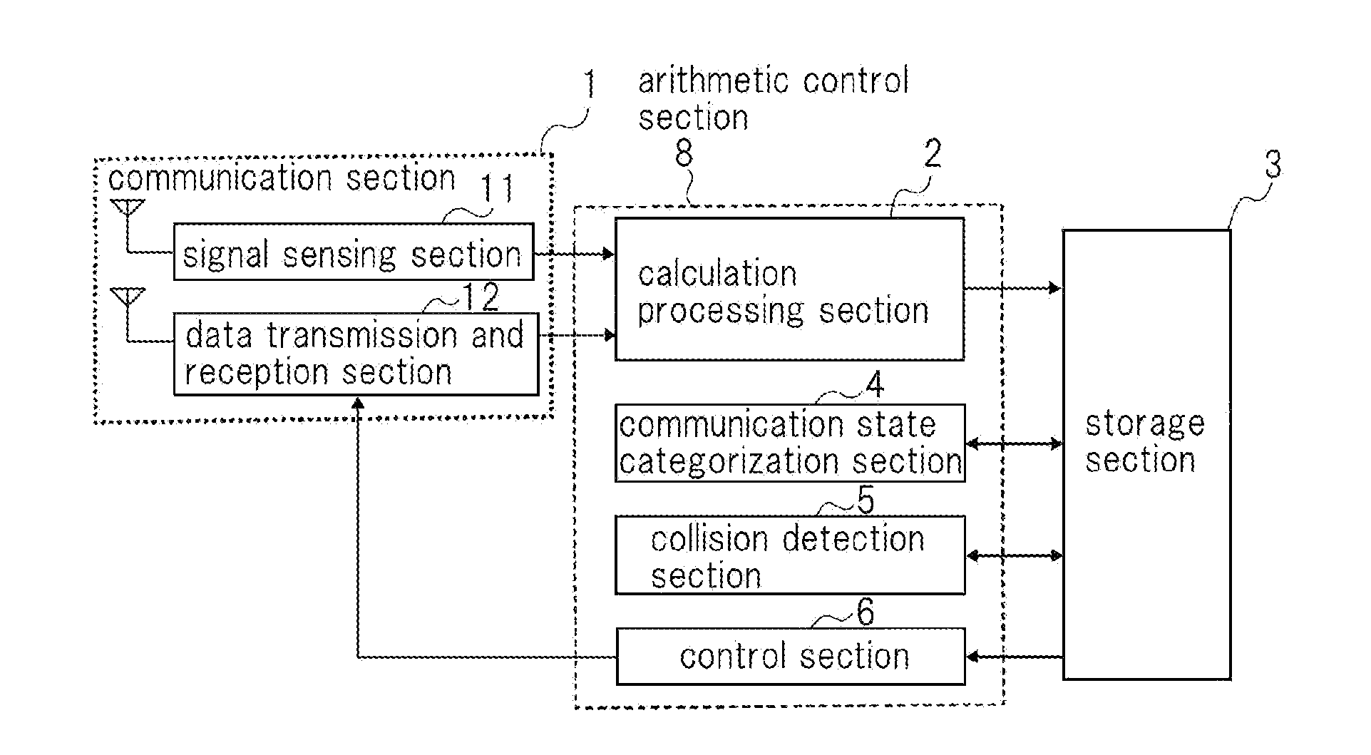
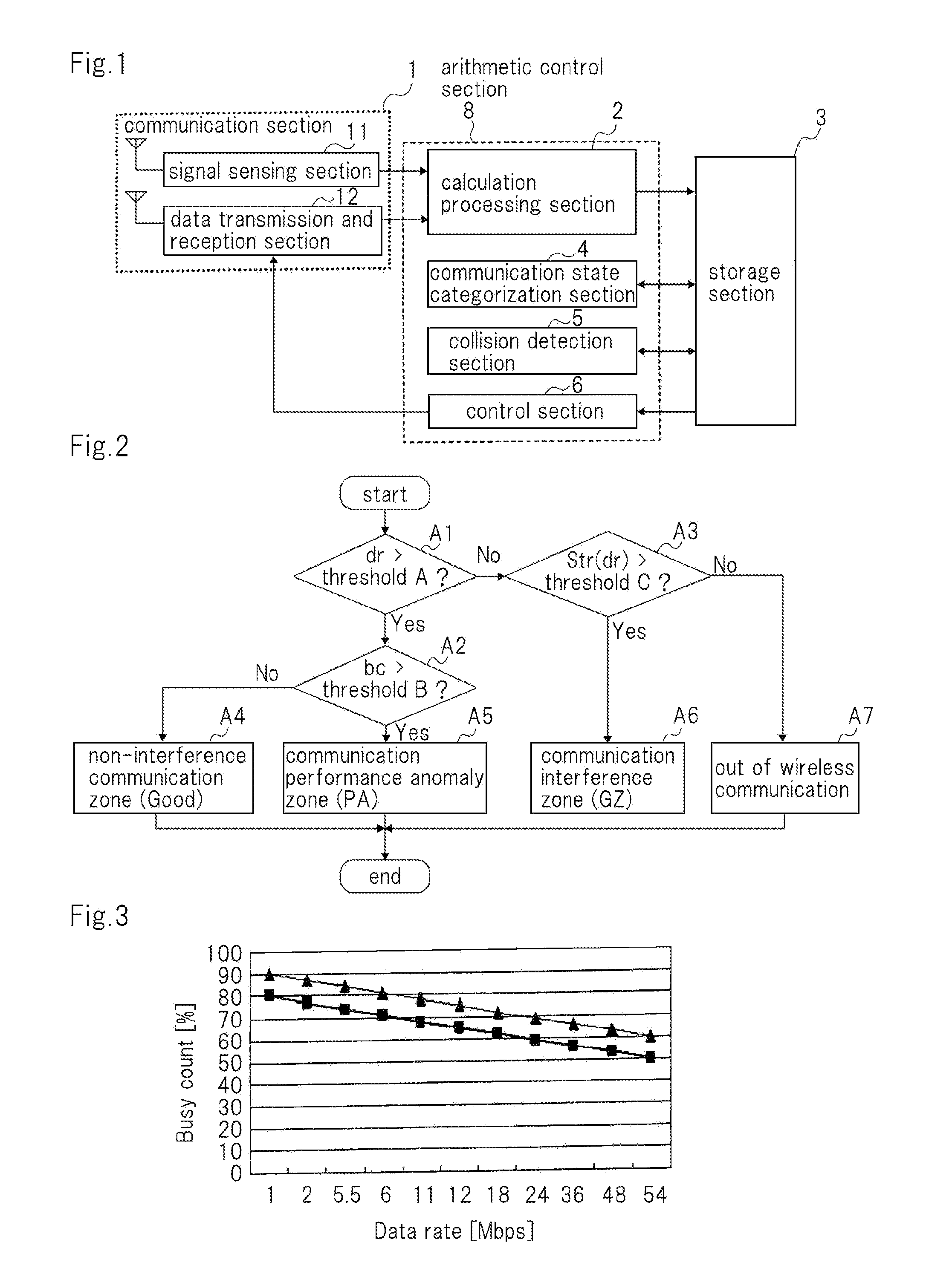
[0038]Next, a structure of the wireless communication device according to a first embodiment will be described. FIG. 1 is a block diagram showing an example of the structure of the wireless communication device according to this embodiment.

[0039]As shown in FIG. 1, the wireless communication device according to this embodiment has communication section 1 that performs data communication and signal sensing; calculation processing section 2 that performs an initial process for a reception signal and calculates communication evaluation parameters; storage section 3 that stores information; communication state categorization section 4 that categorizes the communication state of its own device that suffers from interference with another communication; collision detection section 5 that detects a communication collision and evaluates it; and control section 6 that adjusts communication performance of communication section 1.

[0040]Arithmetic control section 8 includes calculation processin...

second embodiment

[0126]Next, with reference to the accompanying drawings, a wireless communication device according to a second embodiment of the present invention will be described. For the sake of simplicity, a detailed description of structural sections similar to those of the first embodiment will be omitted.

[0127]FIG. 13 is a block diagram showing an example of a structure of the wireless communication device according to this embodiment. As shown in FIG. 13, the wireless communication device according to this embodiment has communication section 1, calculation processing section 2, storage section 3, communication state categorization section 4, and control section 6. According to this embodiment, communication section 1 is provided with data transmission and reception section 12 instead of signal sensing section 11 shown in FIG. 1.

[0128]The wireless communication device according to this embodiment is not provided with signal sensing section 11 and collision detection section 5 shown in FIG. ...

third embodiment

[0130]Next, with reference to the accompanying drawings, a wireless communication device according to a third embodiment of the present invention will be described. For the sake of simplicity, a detailed description of structural sections similar to those of the first embodiment will be omitted.

[0131]FIG. 14 is a block diagram showing an example of the structure of the wireless communication device according to this embodiment. As shown in FIG. 14, the wireless communication device according to this embodiment has communication section 1, calculation processing section 2, storage section 3, collision detection section 5, and control section 6.

[0132]The wireless communication device according to this embodiment is not provided with communication state categorization section 4 shown in FIG. 4. Thus, according to this embodiment, the transmission parameter that improves the transmission efficiency is adjusted based on the result that is output from collision detection section 5.

[0133]A...


PUM


Abstract

A wireless communication device includes a data transmission and reception section that wirelessly transmits a plurality of test packets; a signal sensing section that senses a power of a spatial radio wave signal on a frequency channel that is the same as the plurality of test packets and outputs sample data of the sensed spatial radio wave signal; a calculation processing section that converts the sample data into time series sample data; a collision detection section that calculates a packet collision rate based on the number of packet collisions and the number of the plurality of test packets if there is a packet collision due to interference of the plurality of test packets with another communication; and a control section that adjusts a parameter that the data transmission and reception section uses based on a calculation result of the collision detection section.

Description

[0001]This application is based upon and claims the benefit of priority from Japanese Patent Application No. 2011-132314 filed on Jun. 14, 2011, the content of which is incorporated by reference.BACKGROUND OF THE INVENTION[0002]1. Field of the Invention[0003]The present invention relates to a wireless communication device, a network, a wireless communication method, and a program that causes a computer to execute the method.[0004]2. Description of Related Art[0005]In recent years, wireless LAN (Local Area Network) communication has become common not only in companies' workplaces, but also in a variety of fields including homes and outdoors. Because the use of wireless LAN has become widespread, there has been an increase in the traffic in available frequency resources, that are limited, thereby creating serious concern about communication interference.[0006]IEEE 802.11, which is one of the wireless LAN standards, uses an access control technique that is referred to as carrier sense ...

Claims


Application Information

Patent Timeline
Patent Type & Authority Applications(United States)
IPC IPC(8): H04W24/00
CPCH04W24/02H04W24/06H04W74/0825H04L41/0654H04L43/0805H04W88/02
Inventor SHAO, PENGAUST, STEFANMATSUMOTO, AKIRAITO, TETSUYADAVIS, PETER
Owner NEC COMM SYST
Learn More