Distributed Link Aggregation Group (LAG) for a Layer 2 Fabic

a technology of link aggregation and layer 2 data network, applied in data switching networks, high-level techniques, digital transmission, etc., can solve the problems of limiting flexibility, artificially reducing aggregate network bandwidth, and inefficient utilization of aggregate network bandwidth

Active Publication Date: 2012-12-20
IBM CORP
View PDF22 Cites 111 Cited by
  • Summary
  • Abstract
  • Description
  • Claims
  • Application Information

AI Technical Summary

Problems solved by technology

These demands have exposed weaknesses in STP and have generated significant industry interest in replacing STP with a more robust, efficient, and flexible Layer 2 protocol.
For example, because STP permits only a single active network path between any two network nodes and blocks all alternate network paths, aggregate network bandwidth is artificially reduced and is inefficiently utilized.
STP also reacts to even small topology changes and may force partitioning of virtual LANs due to network connectivity changes.
In addition, the Ethernet header of STP frames does not include a hop count (or Time to Live (TTL)) field, limiting flexibility.
Furthermore, because only a single active network link is supported between any two nodes, STP has poor fault tolerance, lengthy failure recovery (which can require broadcast traffic to relearn forwarding paths) and low reliability (i.e., dropped traffic).

Method used


Image

  • Distributed Link Aggregation Group (LAG) for a Layer 2 Fabic
  • Distributed Link Aggregation Group (LAG) for a Layer 2 Fabic
  • Distributed Link Aggregation Group (LAG) for a Layer 2 Fabic

Examples


Embodiment Construction

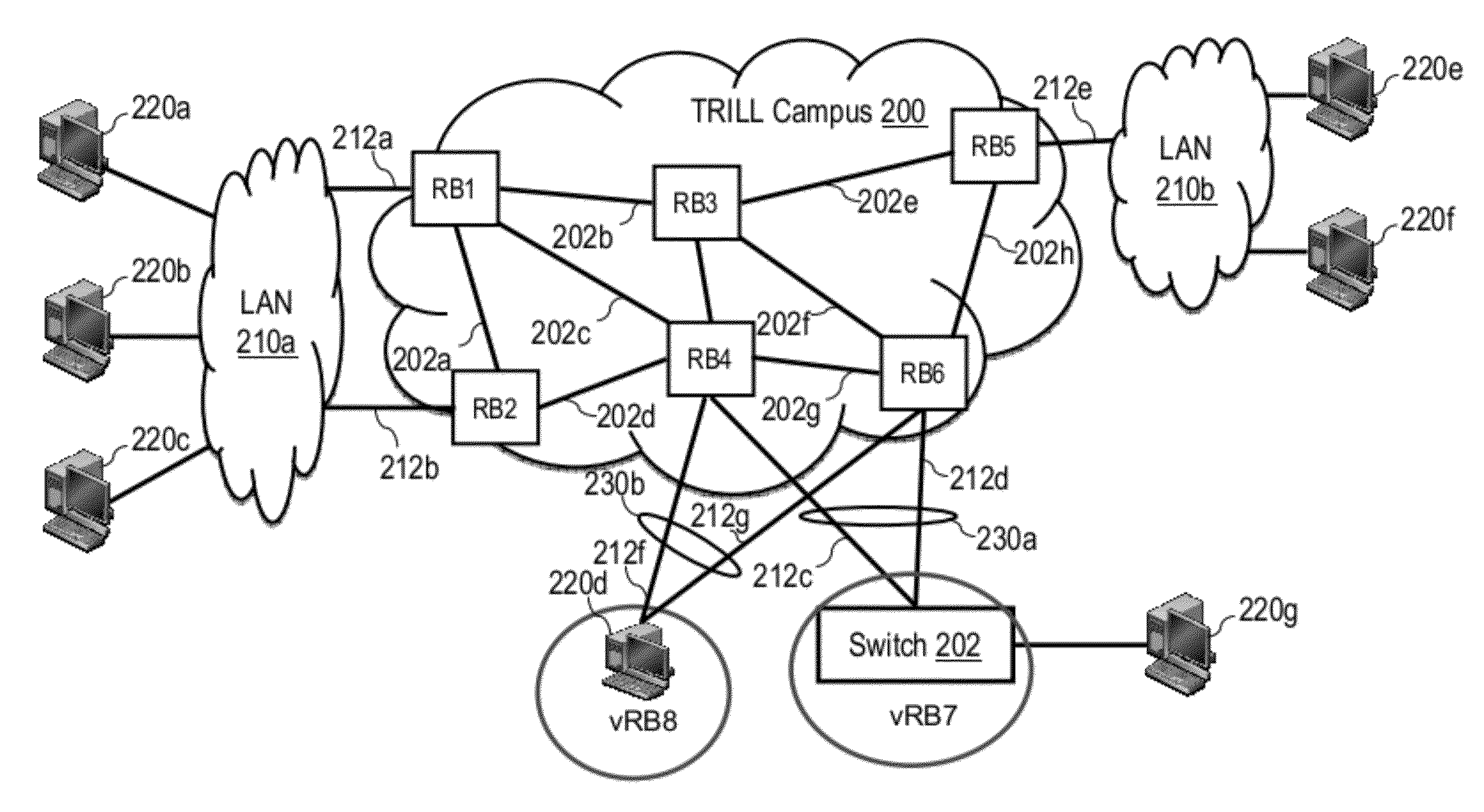
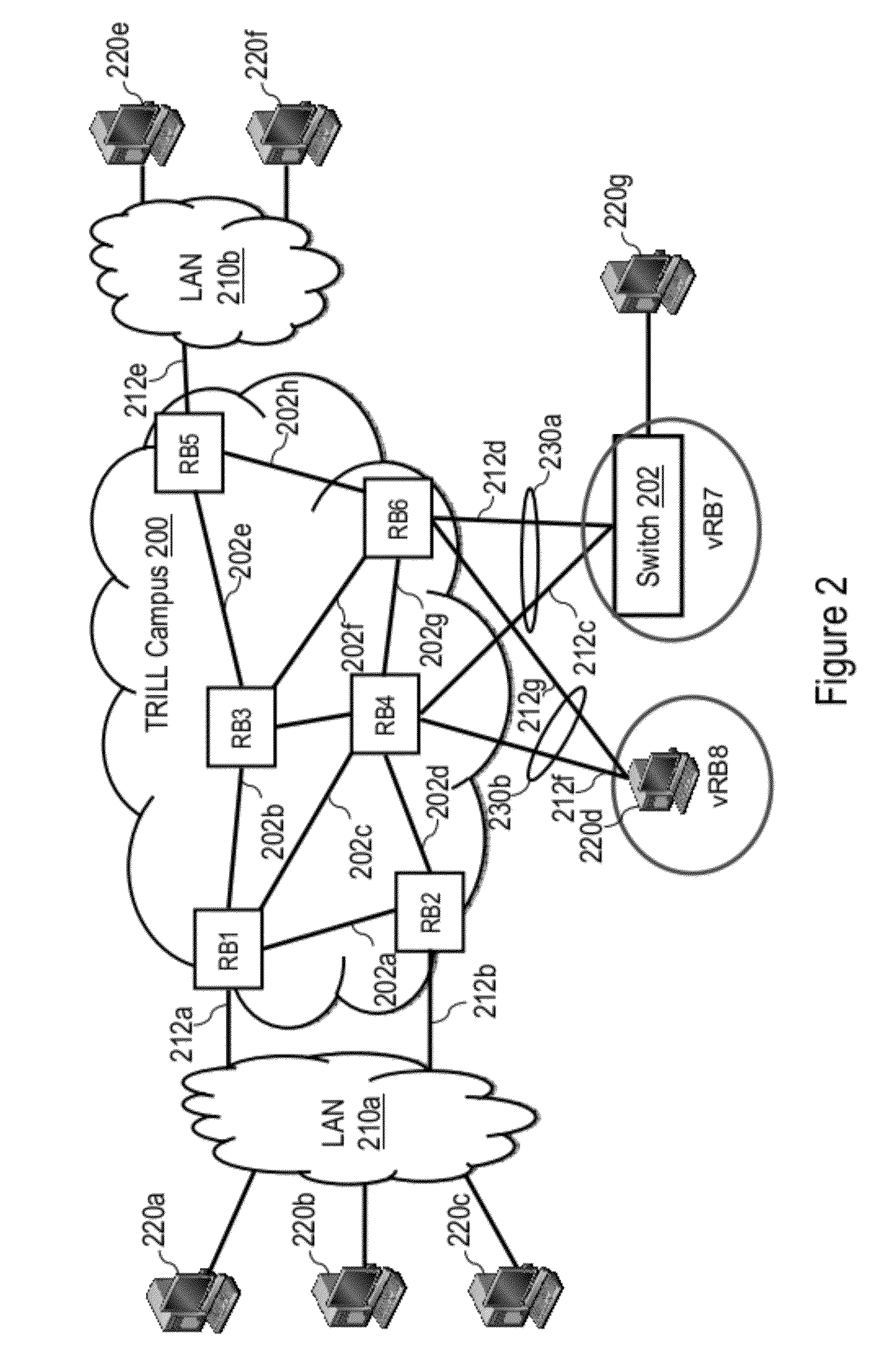
[0042]The present application describes mechanisms and associated methodologies, referred to herein as TRILL LAG or t-LAG, that facilitate the connection of network nodes (e.g., servers and / or switches) external to a TRILL campus in a Link Aggregation Group (LAG) through the use of a virtual routing bridge (virtual-RB). Multiple t-LAGs may additionally be hosted by a set of multiple physical switches, herein referred to as a t-LAG cluster, with all t-LAGs in a given t-LAG cluster preferably (but not necessarily) sharing the same virtual-RB. The use of the virtual-RB for the t-LAGs can resolve load distribution for unicast (UC) traffic. For multidestination (e.g., multicast (MC), broadcast (BC), destination lookup fail (DLF)) traffic, different mechanisms are employed to ensure traffic is properly delivered to a peer RB of a t-LAG cluster; otherwise, either more than one copy of a multidestination frame may be sent to the same destination or a frame may be erroneously returned to an ...


PUM


Abstract

Each of first and second bridges of a data network having respective links to an external node implement a network bridge component that forwards traffic inside the data network and a virtual bridge component that forwards traffic outside of the data network. A virtual bridge is formed including the virtual bridge components of the first and second bridges and an interswitch link (ISL) between the virtual bridge components of the first and second bridges. Data frames are communicated with each of multiple external network nodes outside the data network via a respective one of multiple link aggregation groups all commonly supported by the virtual bridge.

Description

PRIORITY CLAIM[0001]The present application claims priority to U.S. Provisional Patent Application 61 / 498,316, filed Jun. 17, 2011.BACKGROUND OF THE INVENTION[0002]1. Technical Field[0003]The present invention relates in general to data networks, and in particular, to a link aggregation group (LAG) for a Layer 2 data network, such as a Transparent Interconnection of Lots of Links (TRILL) network.[0004]2. Description of the Related Art[0005]The IEEE 802.1D standard defines the Spanning Tree Protocol (STP), which is a conventional data link layer protocol that ensures that a bridged Ethernet network is free of bridge loops and that a single active network path exists between any given pair of network nodes. Current trends for packet-switched data networks—including the convergence of local area network (LAN) and storage area network (SAN) traffic (e.g., Fibre Channel, Fibre Channel over Ethernet (FCoE), Internet Small Computer System Interface (iSCSI), etc.), rapidly increasing bandwi...

Claims


Application Information

Patent Timeline
Patent Type & Authority Applications(United States)
IPC IPC(8): H04L12/56H04L45/243H04L45/28
CPCH04L45/66H04L45/245Y02D50/30H04L41/0654H04L45/28Y02D30/50
Inventor KAMATH, DAYAVANTI G.KAMBLE, KESHAVLEU, DAR-RENMUKHERJEE, NILANJANPANDEY, VIJOY A.
Owner IBM CORP
Why Eureka
Try Eureka