Trigger wire activation lever

a technology of trigger wires and levers, which is applied in the field of prosthesis deployment, can solve the problems of increasing the difficulty of the operator of the deployment device to pull a knob and remove the trigger wire, and providing significant loads on the trigger wire actuation mechanism

Active Publication Date: 2012-12-20
COOK MEDICAL TECH LLC
View PDF10 Cites 13 Cited by
  • Summary
  • Abstract
  • Description
  • Claims
  • Application Information

AI Technical Summary

Benefits of technology

[0006]The present disclosure relates to providing a prosthesis deployment system that overcomes at least some of the issues discussed above or at least provides an alternative arrangement of conventional prosthesis deployment systems.

Problems solved by technology

It has been found that deployment of stent grafts with multiple trigger wires as well as the general friction of interacting components can provide significant loads on trigger wire actuation mechanisms.
Thus, the force necessary to pull a knob and remove trigger wires becomes increasingly difficult for the operator of the deployment device.

Method used


Image

  • Trigger wire activation lever
  • Trigger wire activation lever
  • Trigger wire activation lever

Examples


Embodiment Construction

[0023]Throughout this specification, the terms proximal and proximally are used for a position or direction towards the patient's heart, and the terms distal and distally are used for a position or direction away from the patient's heart. When applied to other vessels, corresponding terms such as caudal and cranial should be understood.

[0024]The construction of embodiments and the methods by which the devices disclosed herein may be operated may be made clearer with the aid of the accompanying drawings. For clarity, the lumens or vessels into which the prosthesis is inserted are not shown in the drawings.

[0025]In the drawings:

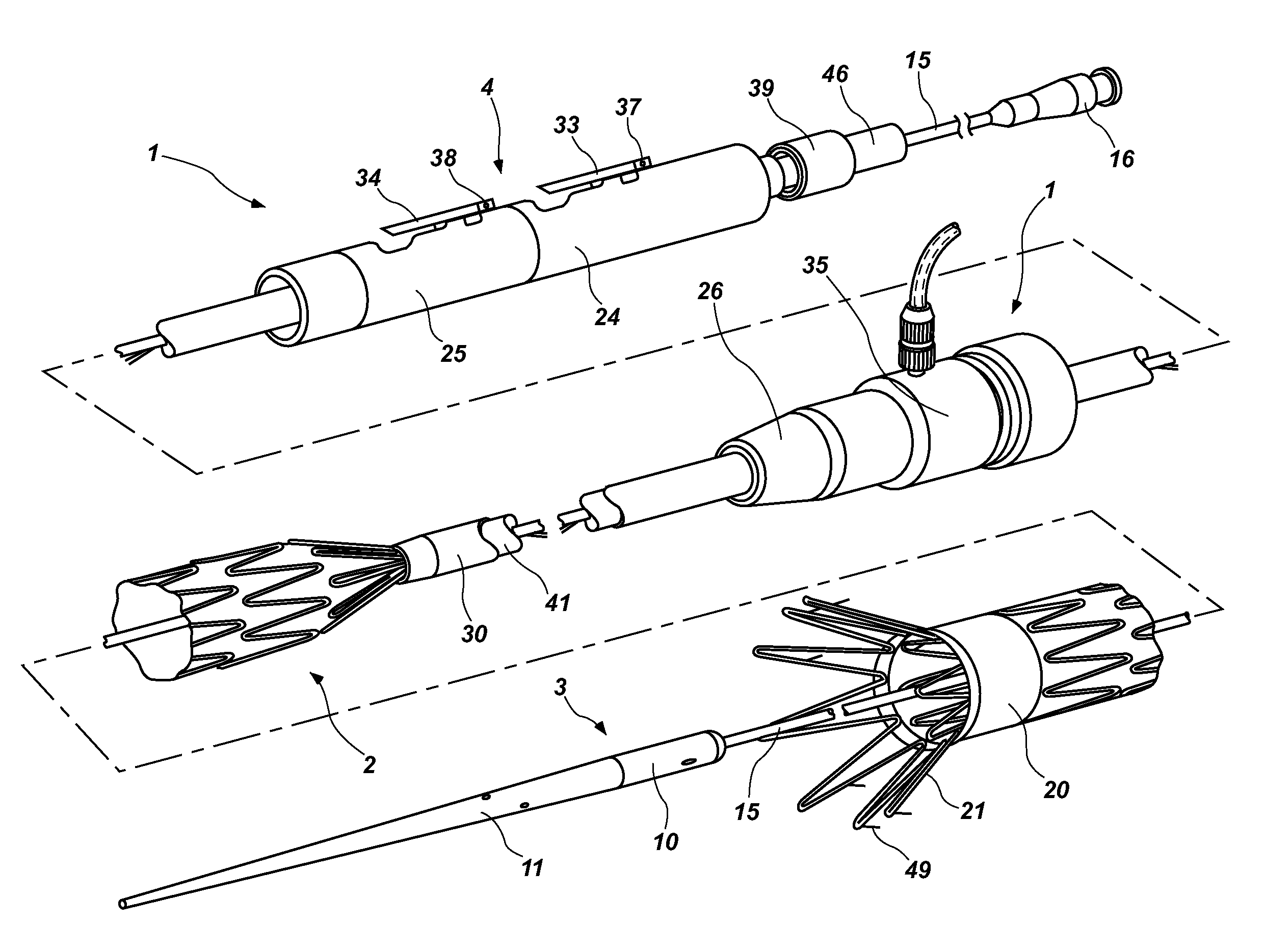
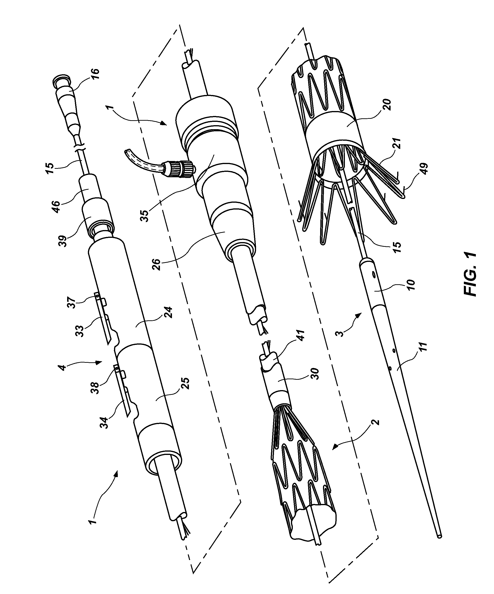
[0026]FIG. 1 shows a first embodiment of an introducer in perspective view with the prosthesis partially deployed;

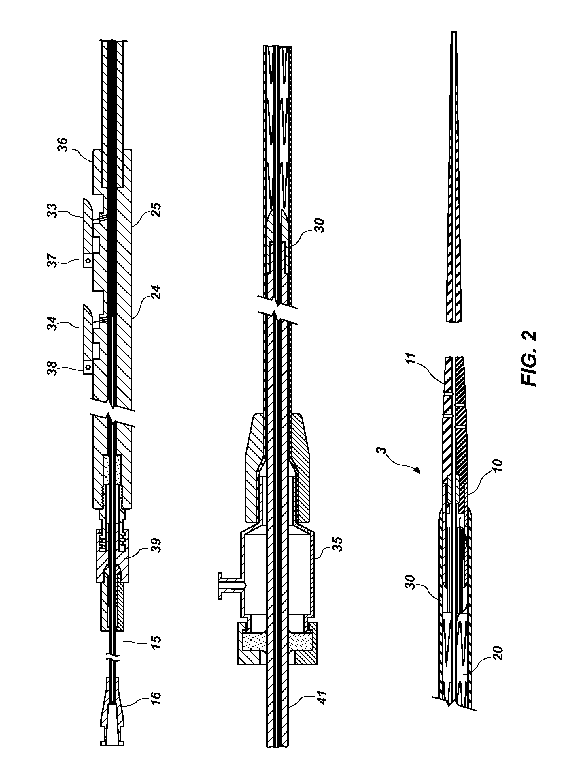
[0027]FIG. 2 shows the first embodiment of the introducer as shown in FIG. 1 being fully loaded and ready for introduction into a patient;

[0028]FIG. 3 shows the embodiment of FIG. 2 in the next stage of deployment of the prosthesis;

[0029]FIG. 4 show...


PUM


Abstract

An actuation assembly having at least one lever operably connected to one or more trigger wires which are operably connected to a stent retaining device for a stent graft introducer is disclosed. The lever or levers can be extended or detached from the introducer to remove the trigger wires.

Description

REFERENCE TO EARLIER FILED APPLICATION[0001]This application claims the benefit under 35 U.S.C. §119(e) of U.S. Provisional Patent Application No. 61 / 498,039, filed Jun. 17, 2011, and titled “TRIGGER WIRE ACTIVATION LEVER,” which is incorporated, in its entirety, by this reference.TECHNICAL FIELD[0002]The present invention relates to prosthesis deployment and more particularly to controlled, trigger wire deployment devices for endovascular stent grafts and methods of actuating such devices.BACKGROUND[0003]Deployment devices are used to deploy prostheses and, in particular, prostheses having self-expanding stents within lumens in the human body.[0004]In some forms of prosthesis deployment, device trigger wires are used to restrain a prosthesis in a particular position on a deployment device, for example self-expanding stents in a retracted state. Increasingly complex prosthesis deployment devices incorporate multiple trigger wires, for example 4-6 trigger wires, to afford more contro...

Claims


Application Information

Patent Timeline
Patent Type & Authority Applications(United States)
IPC IPC(8): A61F2/84
CPCA61F2/95A61F2002/9511A61F2002/9517A61F2/9517
Inventor BRINSER, STEVEN
Owner COOK MEDICAL TECH LLC
Why Eureka
Try Eureka