
Stirred tank bioreactor

a bioreactor and tank technology, applied in bioreactors/fermenters, biomass after-treatment, biochemical apparatus and processes, etc., can solve the problems of wrinkles in the liner, time-consuming, laborious process,

Active Publication Date: 2015-04-07
MILLIPORE CORP
View PDF235 Cites 8 Cited by
  • Summary
  • Abstract
  • Description
  • Claims
  • Application Information

AI Technical Summary

Benefits of technology

The present invention is a bioreactor made of molded plastic that can be held in a stand or self-standing. It has one or more ports for sampling and probe attachment. The molded design eliminates issues of discontinuity and dead spots and allows for reproducible probe location. The rigid bowl can accept the heating blanket, which means there is no need for an external support or heating jacket. The molded plastic allows for greater flexibility in material selection, reducing or eliminating lipid or cholesterol binding. The molded containers are self-supportive and do not require a support housing. Heating or cooling blankets can be directly attached to the molded body. The one or more ports formed below the liquid / air level have a drain that allows for easy removal of all liquid when desired.

Problems solved by technology

This is a time consuming, laborious process requiring the disassembly and moving of many heavy and / or small and fragile components.
However, it too has many limitations.
However wrinkles in the liner still occur and create the above mentioned problems.
All ports are top mounted, limiting the available area for the different components used in the bioreactor (feed lines, airlines, stirrer shafts, motors and journals, sampling ports, probe ports and the like).
Often times the liner system is limited to an air sparging system for both gas transfer and circulation.
This means that there is often a long dead leg of material that needs to be flushed or removed before and after sampling to ensure that an accurate sample has been obtained.

Method used


Image

  • Stirred tank bioreactor
  • Stirred tank bioreactor
  • Stirred tank bioreactor

Examples


Embodiment Construction

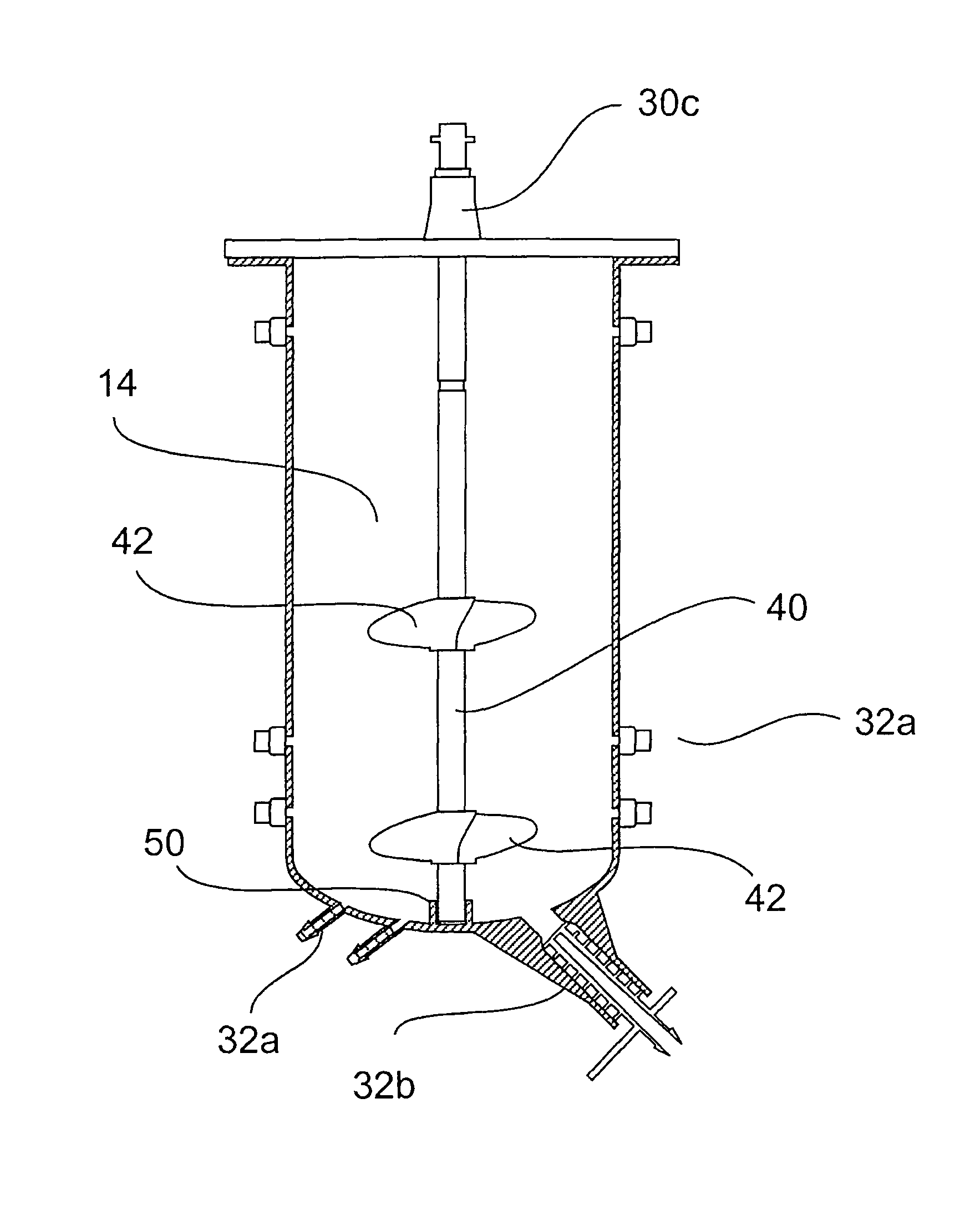
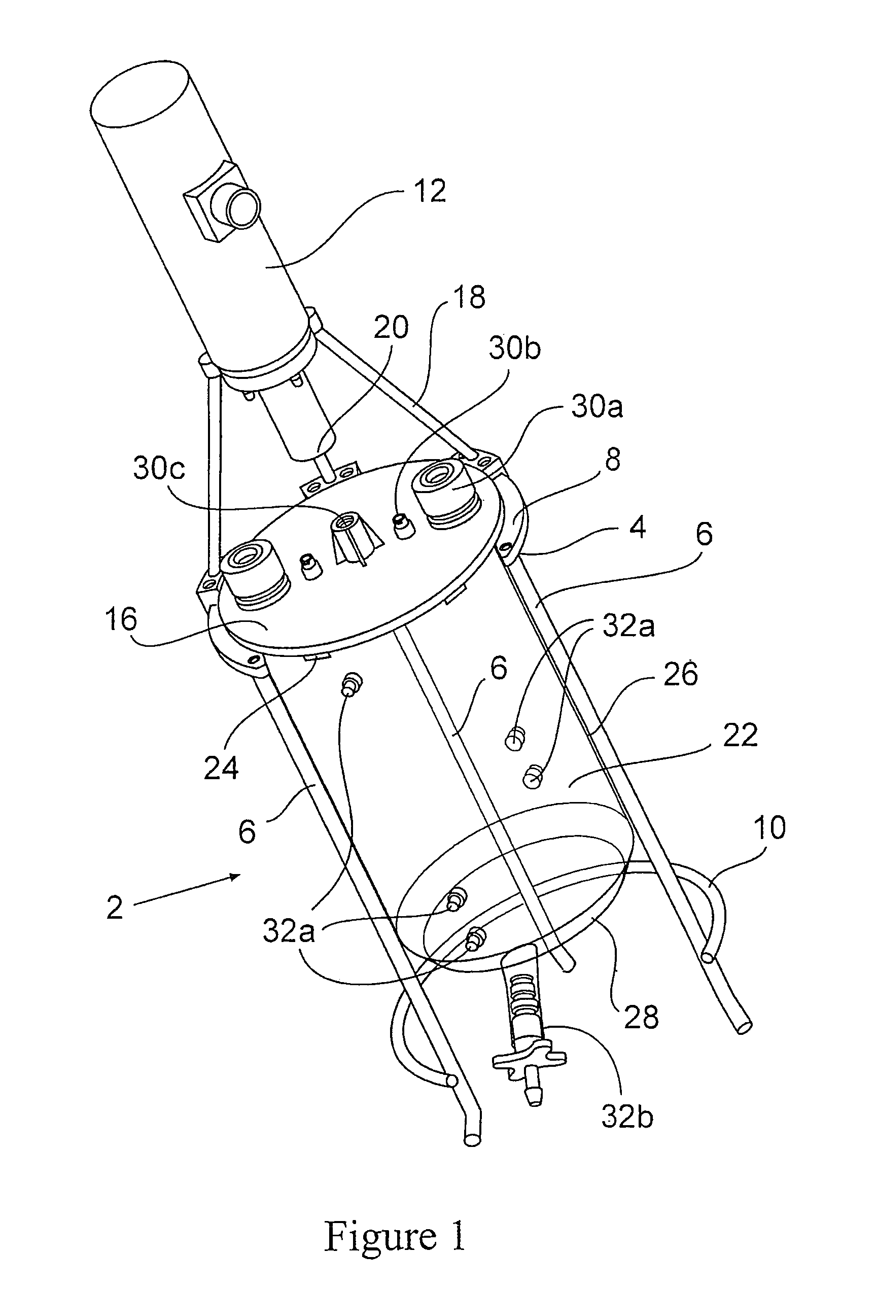
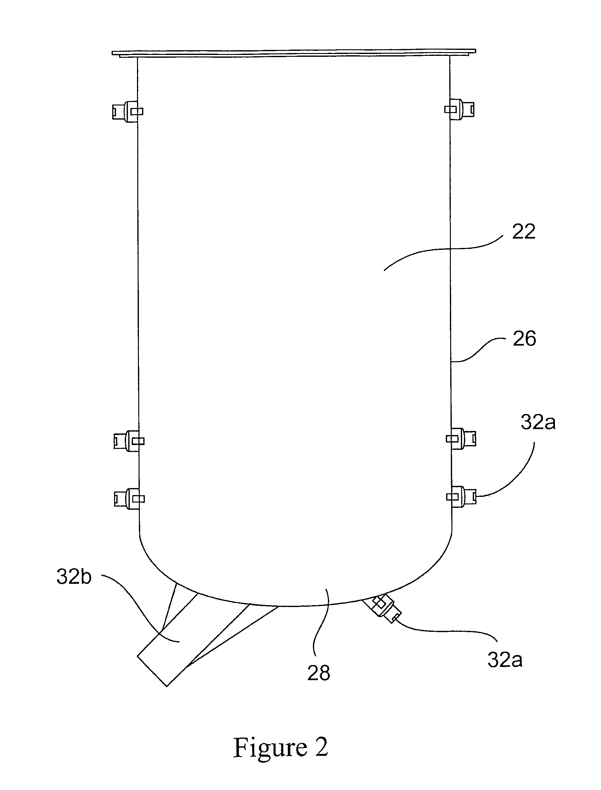
[0031]FIG. 1 shows an embodiment of the present invention. The bioreactor 2 is held in a stand 4 which is comprised of several legs 6 (in this embodiment 3 legs although one continuous leg or 2 large legs or more than 3 legs can also be used) and a support rim 8. As shown the legs 6 may have an optional support piece 10 at or near the bottom to keep the legs 6 from spreading when the bioreactor 2 is filled and in the stand 4.

[0032]Depending upon the type of circulation system used the stand 4 may also support the drive mechanism 12 (as shown) for the circulation mechanism, which typically is a stirrer or paddle assembly 14 as will be described in greater detail later. In this particular embodiment, the drive mechanism 12 is a motor and is mounted to the top of the centered above the top 16 of the bioreactor 2 by several arms 18 (although 3 are shown alternative numbers may be used). Other features such as mounting blocks (not shown) and the like may be formed on the top 16 or suppor...


PUM

PropertyMeasurementUnit
volumesaaaaaaaaaa
sizeaaaaaaaaaa
fragileaaaaaaaaaa

Abstract

The present invention is a disposable bioreactor formed of molded plastic. The bioreactor is presterilized and has a top and body sealed to each other. One or more ports are formed in the top and side of the housing. Preferably at least one port is below the liquid / air level for the housing. The one or more ports that are below the liquid / air interface level may be used as sampling ports or access ports for probes or drains or supply ports for liquids or gases. The bioreactor provides a direct retrofit for the existing glass or steel assembly that utilizes the existing support structures and controls. The molded design overcomes issues of discontinuity, dead spots and the like due to its fixed dimensions that are built in by the molding process. Reproducible probe and other equipment location is also guaranteed through the use of the molded port features. The molded plastic allows for greater flexibility in material selection to reduce or eliminate lipid or cholesterol binding.

Description

CROSS-REFERENCED TO RELATED APPLICATIONS[0001]This application claims the benefit of U.S. Provisional Patent Application No. 61 / 131,640, filed on Jun. 11, 2008, the entire contents of which are incorporated by reference herein.[0002]The present invention relates to a disposable stirred tank bioreactor. More particularly, it relates to a stirred tank reactor formed of a molded plastic having one or more ports molded therein.BACKGROUND OF THE INVENTION[0003]Many small scale bioreactors of the size from about 1 liter to about 200 liters are formed of glass or steel, preferably stainless steel. Typical volumes for bench top versions are 2-10 liters. All have a solid body and a removable top sealed to the body by an o-ring. The top contains ports for probes, sampling, air sparging, media exchange, and a stir rod for circulation. They are typically used for culturing or fermenting various organisms such as plants, bacteria (e.g. E. coli), animal cells (e.g. Chinese Hamster Ovary (CHO) cel...

Claims


Application Information

Patent Timeline
Patent Type & Authority Patents(United States)
IPC IPC(8): C12M1/00C12M1/02C12M3/00
CPCC12M23/28C12M23/20C12M27/00C12M23/48C12M1/02C12M1/06C12M23/38C12M23/46C12M29/00
Inventor KELLY, JR., JAMES E.MULDOON, JOSEPH WILLIAMPROULX, STEPHENVIGNA, JAMES
Owner MILLIPORE CORP
Learn More