
Cutting apparatus for adhesive tape rolls

a cutting apparatus and adhesive tape technology, applied in metal working apparatus, manufacturing tools, transportation and packaging, etc., can solve the problems of increased cutting resistance, unclean cut-surfaces, deviated cantilevered blade shafts, etc., to reduce cutting-in angles, prevent shifting or bending of blade shafts, and prevent the effect of circular blade shifting

Inactive Publication Date: 2012-12-27
NITTO DENKO CORP
View PDF18 Cites 0 Cited by
  • Summary
  • Abstract
  • Description
  • Claims
  • Application Information

AI Technical Summary

Benefits of technology

[0010]In the adhesive tape roll cutting apparatus having the cantilevered blade shaft for the circular blade, the circular blade is easily attached or detached from the free end of the blade shaft; however, when the circular blade is pressed against the body of the adhesive tape roll, the cantilevered blade shaft is deviated. Due to this, the circular blade for cutting the adhesive tape roll is easily deviated. This shifting of the circular blade causes the convex and concave cut-surfaces, and straight cut-surfaces are not obtained, which consequently leads to defectives. Further, the convex and concave cut-surfaces cause the adhesive agent on the adhesive tape roll to easily exude. This may result in adhesion of the adhesive agent on the circular blade, which will lead to unclean cut-surfaces and an increased in the cutting resistance.
[0011]Further, when the blade shaft is bent, the circular blade mounted on the cantilevered blade shaft is easily deviated in a direction of cutting out a tape roll. This necessitates an increase in the angle of tilting the circular blade (hereinafter, cutting-in angle) towards the tape roll main body. Increasing this cutting-in angle of the circular blade causes an increase in the area of the adhesive layers of the adhesive tape roll contacting the circular blade. This causes adhesion of the adhesive agent on the circular blade, thus increasing the cutting resistance.
[0012]In view of the above problems, an object of the present invention is to restrain the deviation of the circular blade, while reducing a cutting-in angle of the circular blade with respect to the tape roll main body.

Problems solved by technology

In the adhesive tape roll cutting apparatus having the cantilevered blade shaft for the circular blade, the circular blade is easily attached or detached from the free end of the blade shaft; however, when the circular blade is pressed against the body of the adhesive tape roll, the cantilevered blade shaft is deviated.
This shifting of the circular blade causes the convex and concave cut-surfaces, and straight cut-surfaces are not obtained, which consequently leads to defectives.
This may result in adhesion of the adhesive agent on the circular blade, which will lead to unclean cut-surfaces and an increased in the cutting resistance.
Further, when the blade shaft is bent, the circular blade mounted on the cantilevered blade shaft is easily deviated in a direction of cutting out a tape roll.

Method used


Image

  • Cutting apparatus for adhesive tape rolls
  • Cutting apparatus for adhesive tape rolls
  • Cutting apparatus for adhesive tape rolls

Examples


Embodiment Construction

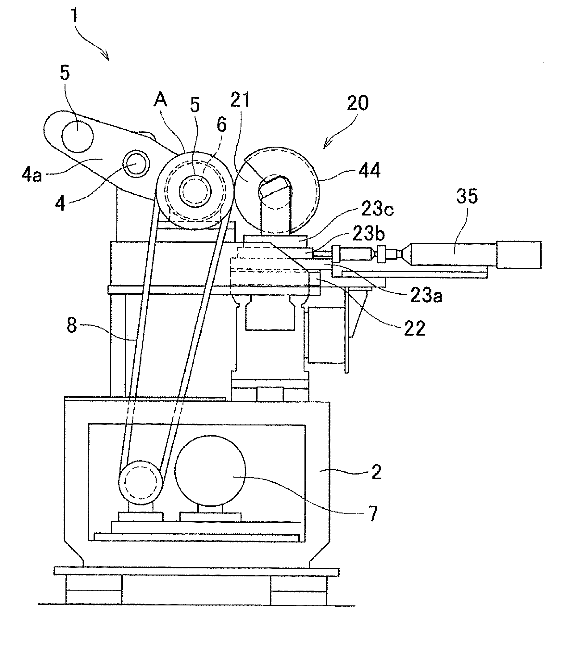
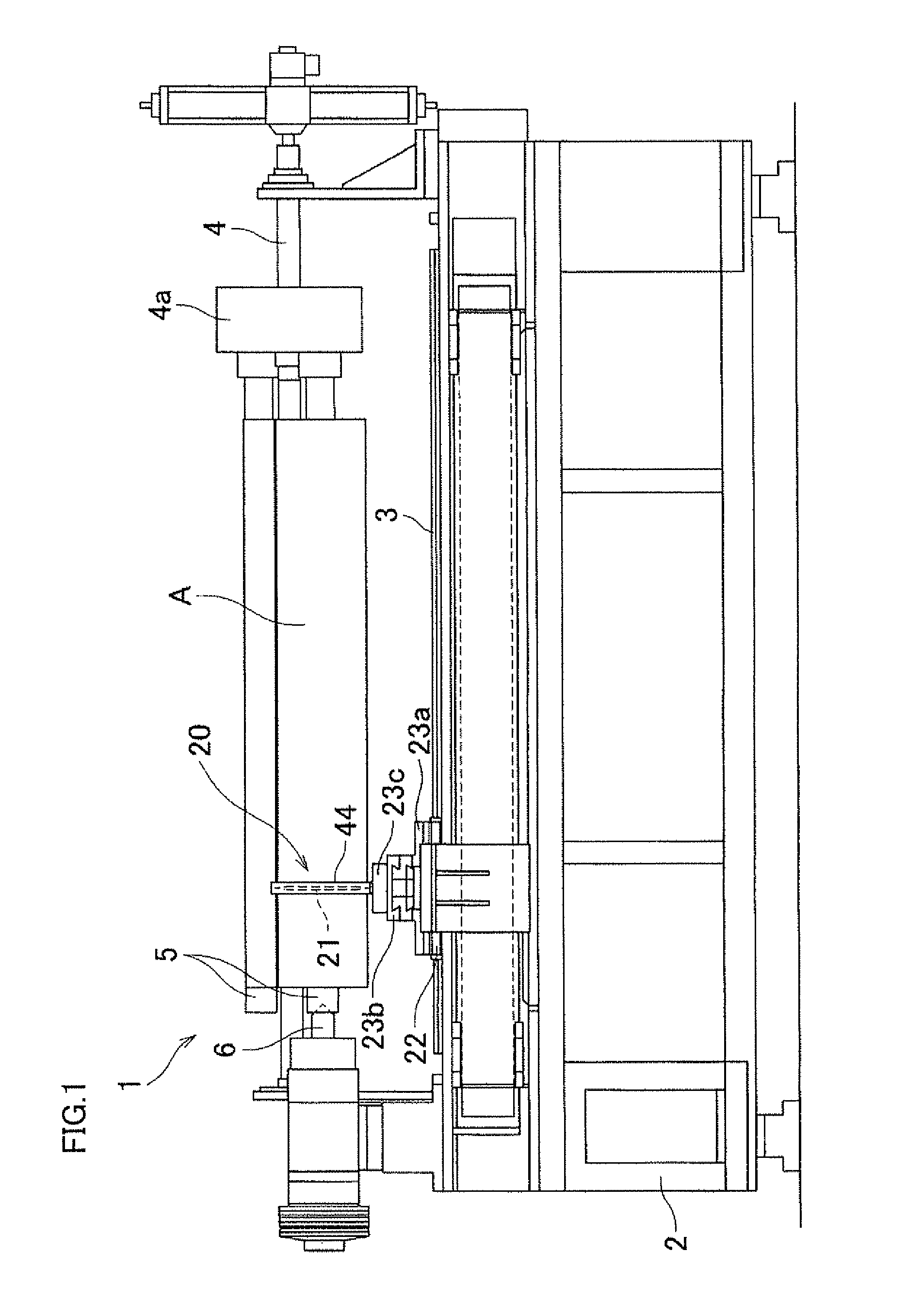
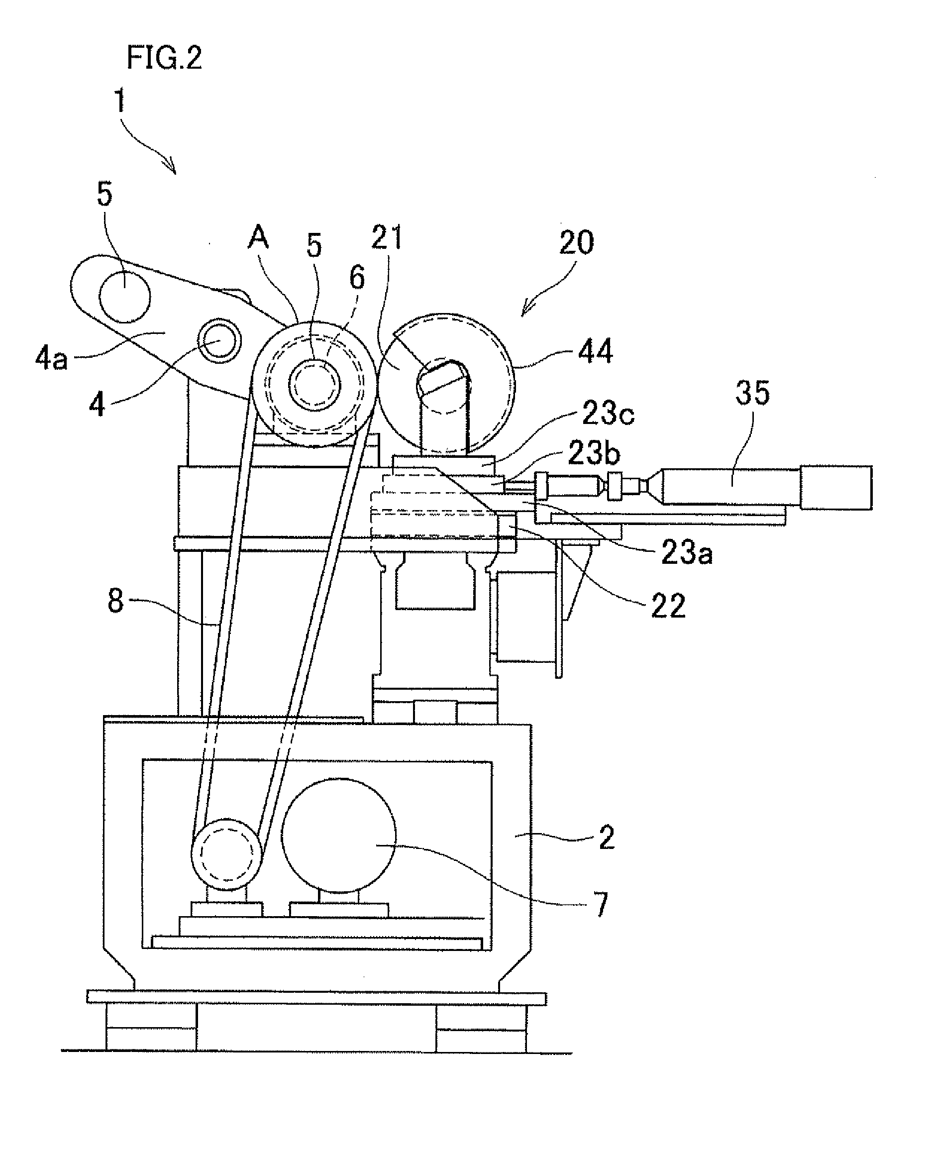
[0024]The following describes an embodiment of the present invention, with reference to attached drawings. As shown in FIG. 1 and FIG. 2, the adhesive tape roll cutting apparatus includes: a tape roll supporting device 1 to which an adhesive tape roll A is rotatably attached, the adhesive tape roll A being formed by rolling on a core wide adhesive tape having an adhesive layer on its one side or the both sides; and a tool post 20 to which a circular blade 21 for cutting in rounds the adhesive tape roll A is rotatably attached. The tool post 20 is attached to the base 2 of the tape roll supporting device 1, and is structured so as to be moved parallel to the axis of the adhesive tape roll A, guided by a guide rail 3.

[0025]The tape roll supporting device 1 has two shaft members 5 and a chuck member 6. The shaft members 5 are cantilevered to not-shown shaft bearings at the both ends of a pivot arm 4a which is turned about the pivot shaft 4 between a front position and a rear position. ...


PUM

PropertyMeasurementUnit
Angleaaaaaaaaaa

Abstract

To restrain shifting of a circular blade, and reduce a cutting-in angle of the circular blade with respect to the tape roll main body, both ends of a rotatable blade shaft 38 is supported by a pair of shaft bearings 39a and 39b of shaft supporting members 37 of a tool post 20. The circular blade 21 is mounted to the blade shaft 38, between the shaft bearings 39a and 39b. This prevents the blade shaft 38 from being shifted or bent, restrains shifting of the circular blade 21, and reduce the cutting-in angle of the circular blade 21 with respect to the tape roll main body.

Description

CROSS REFERENCE TO RELATED APPLICATION[0001]The present application claims priority from Japanese Patent Application No. 2011-140278, which was filed on Jun. 24, 2011, the disclosure of which is herein incorporated by reference in its entirety.BACKGROUND OF THE INVENTION[0002]1. Technical Field[0003]The present invention relates to a cutting apparatus for an adhesive tape roll, which cuts in rounds an adhesive tape roll.[0004]2. Background Art[0005]In many cases, wide adhesive tape with an adhesive layer formed on its one side or both sides is rolled on a core such as a paper tube so as to form an adhesive tape roll. This adhesive tape roll is then cut in rounds at a predetermined width as the end product.[0006]To cut in rounds such an adhesive tape roll, the adhesive tape roll is rotatably attached to a tape roll supporting device. Then a circular blade rotatably attached to a tool post is forwarded perpendicularly to the axis of the adhesive tape roll. Then, while driving (rotatin...

Claims


Application Information

Patent Timeline
IPC IPC(8): B26D1/18
CPCB26D1/18B26D7/2621B26D3/16Y10T83/7693B65H35/06
Inventor SUTOU, SADAJIMATSUE, FUTOSHIOKANO, AKIRA
Owner NITTO DENKO CORP
Learn More