Yard Waste Bag Holding Apparatus

Inactive Publication Date: 2012-12-27
MOYNIHAN JAMES M
View PDF38 Cites 13 Cited by
  • Summary
  • Abstract
  • Description
  • Claims
  • Application Information

AI Technical Summary

Benefits of technology

[0015]FIG. 4 illustrates in more detail the holding of a yard waste bag using the clips of the ring according to an embodiment of the present invention.
[0016]FIG. 5 illustrates in more detail the ring of the yard wast

Problems solved by technology

However, the bags often collapse or tilt during use, which lowers the effici

Method used


Image

  • Yard Waste Bag Holding Apparatus
  • Yard Waste Bag Holding Apparatus
  • Yard Waste Bag Holding Apparatus

Examples


Example

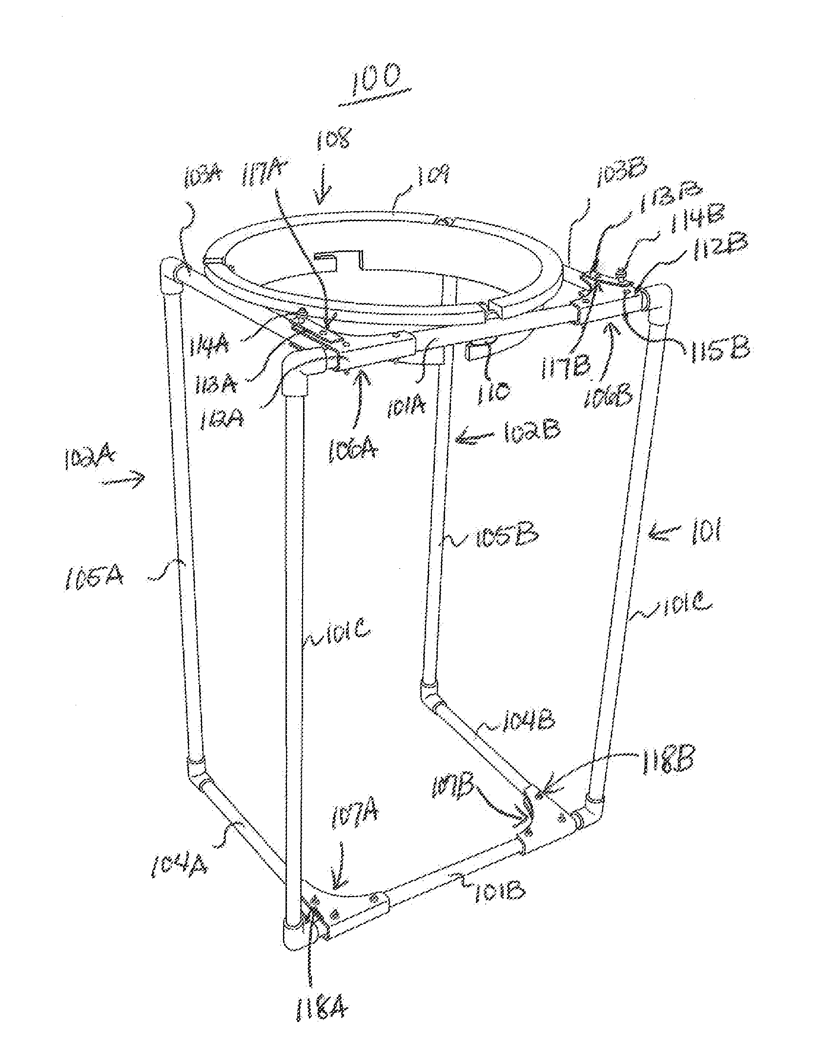
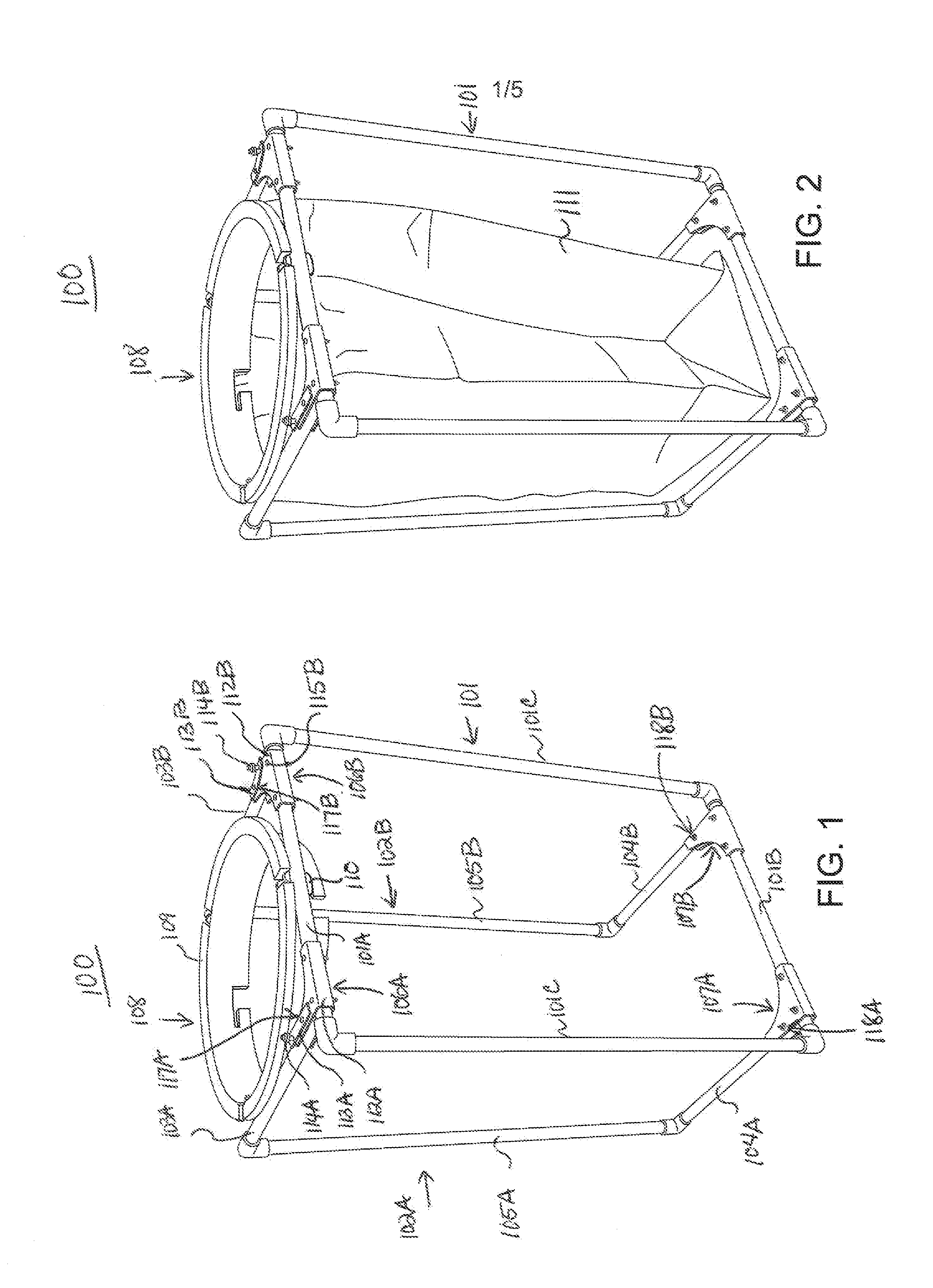
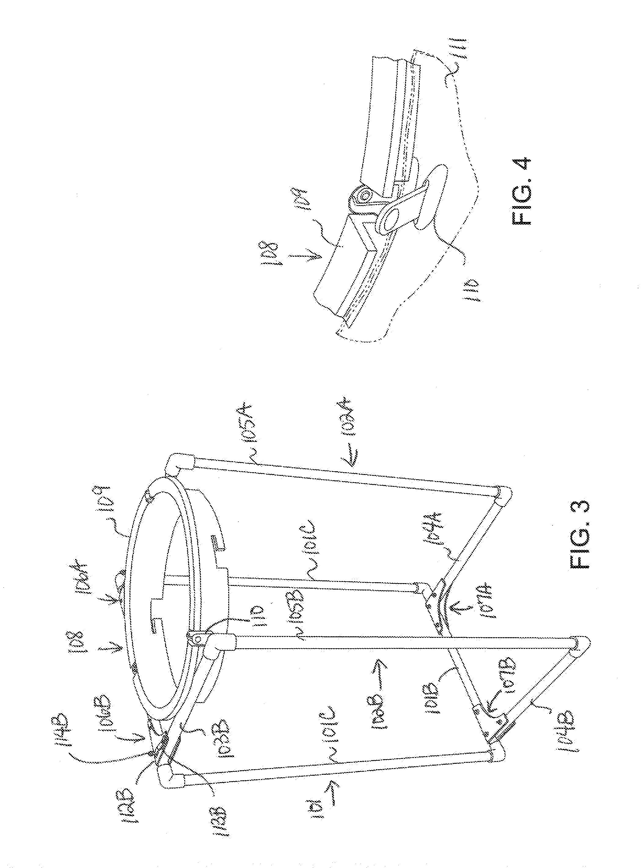
[0023]The present invention provides a yard waste bag holding apparatus. The following description is presented to enable one of ordinary skill in the art to make and use the present invention and is provided in the context of a patent application and its requirements. Various modifications to the embodiment will be readily apparent to those skilled in the art and the generic principles herein may be applied to other embodiments. Thus, the present invention is not intended to be limited to the embodiment shown but is to be accorded the widest scope consistent with the principles and features described herein.

[0024]The terminology used herein is for the purpose of describing particular embodiments only and is not intended to be limiting of the invention. As used herein, the singular forms “a”, “an” and “the” are intended to include the plural forms as well, unless the context clearly indicates otherwise. It will be further understood that the terms “comprises” and / or “comprising,” wh...


PUM


Abstract

A yard waste bag holding apparatus includes a rectangular-shaped frame, two foldable arm assemblies, and a ring with a flange for abutting the top of the arm assemblies. A bag may be attached to the ring, holding the bag open and upright and preventing it from collapsing, folding in on itself, or blowing or tipping over. The user may insert a greater volume of yard waste into the bag at one time, thus increasing efficiency. An insert for engaging a hose of a vacuum to the ring may be added. Further, a wheel attachment may be coupled to the frame to place the apparatus at a given angle. Placing the apparatus at an angle prevents the apparatus from tipping during use with a vacuum and reduces the stress at the joining of the hose and the apparatus.

Description

CROSS-REFERENCE TO RELATED APPLICATIONS[0001]The present application claims priority to co-pending U.S. provisional patent application entitled “Leaf Bag Holding Apparatus”, Ser. No. 61 / 500,713, filed on Jun. 24, 2011, and is incorporated herein in its entirety by reference.BACKGROUND OF THE INVENTION[0002]Yard waste bags are well known in the art. Typically, the bags are opened and set on the ground without support while yard waste is placed inside the bags. However, the bags often collapse or tilt during use, which lowers the efficiency of yard waste gathering and raising the frustration level for the user.BRIEF SUMMARY OF THE INVENTION[0003]According to one embodiment of the present invention, a yard waste bag holding apparatus comprises: a frame, comprising: a first top bar; a first bottom bar; and a first side bars coupled to the first top bar and the first bottom bar to form a rectangular-shaped frame; a first arm assembly, comprising: a second top bar; a second bottom bar; an...

Claims


Application Information

Patent Timeline
IPC IPC(8): B65B67/12
CPCB65B31/048B65B67/1233B65B67/1244B65B67/1266B65F2240/138B65F1/1473B65F2210/179B65F1/127B65F1/1415
Inventor MOYNIHAN, JAMES M.MOYNIHAN, EDWARD J.
Owner MOYNIHAN JAMES M
Why Eureka
Try Eureka