
Rail barrel direct energy transferor piezoelectricity

a direct energy transfer and rail barrel technology, applied in the direction of generators/motors, mechanical equipment, machines/engines, etc., can solve the problem that the flywheel apparatus cannot traverse back

Inactive Publication Date: 2012-12-27
CASTOR VARNELL
View PDF7 Cites 4 Cited by
  • Summary
  • Abstract
  • Description
  • Claims
  • Application Information

AI Technical Summary

Benefits of technology

[0022]These together with additional objects, features and advantages of the rail barrel will be readily apparent to those of ordinary skill in the art upon reading the following detailed description of presently preferred, but nonetheless illustrative, embodiments of the rail barrel when taken in conjunction with the accompanying drawings.
[0023]In this respect, before explaining the current embodiments of the rail barrel in det

Problems solved by technology

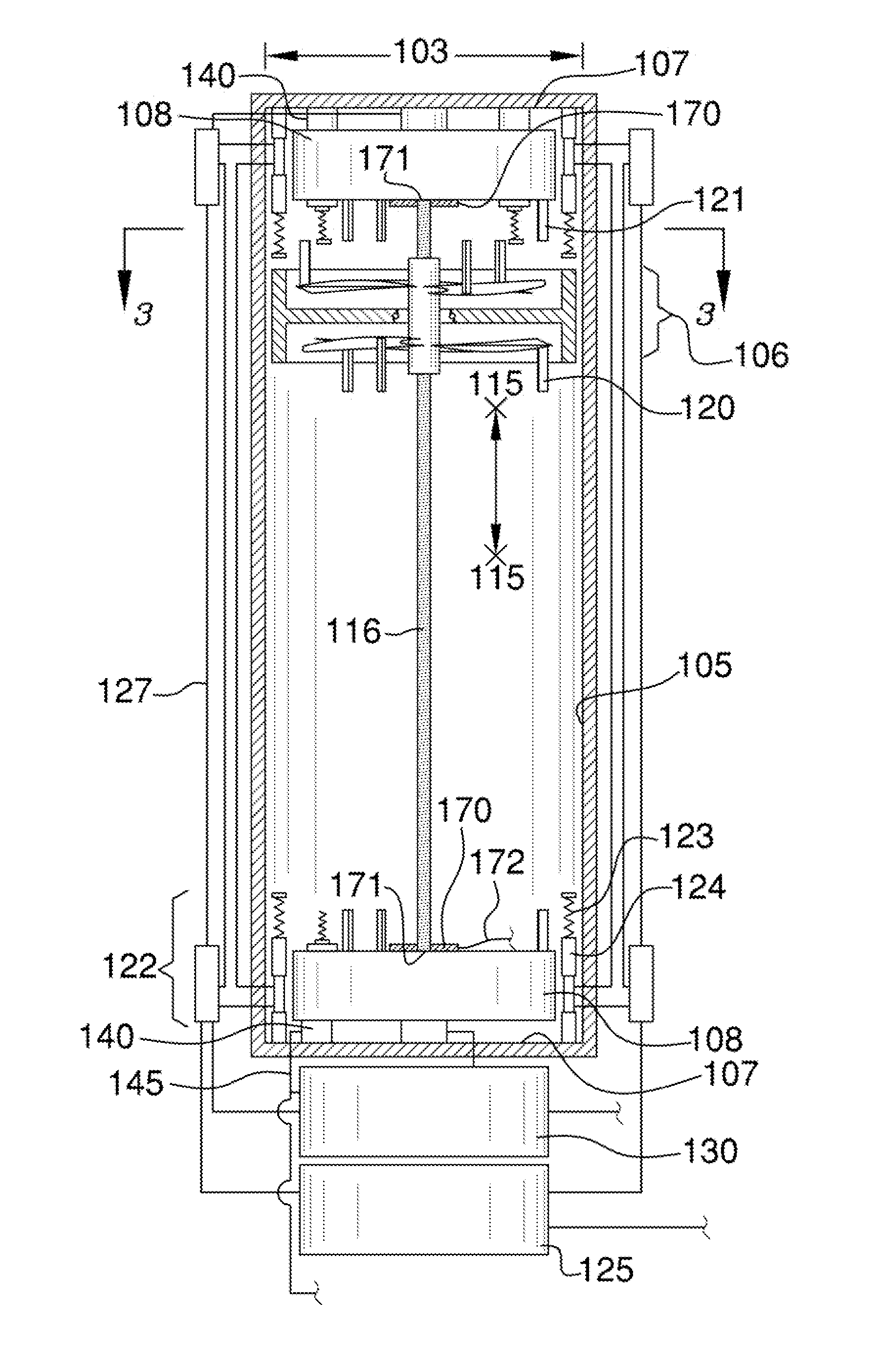
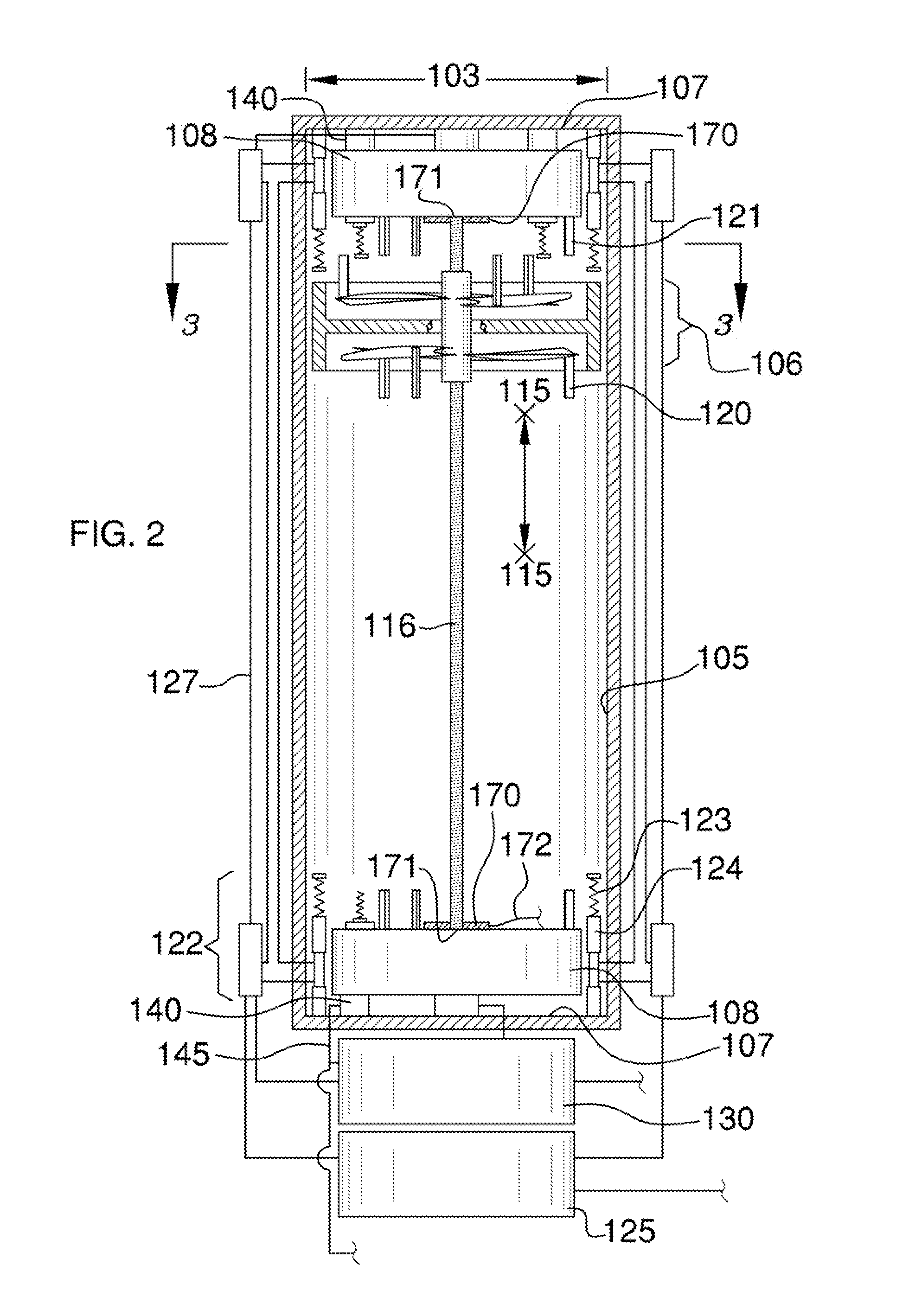
However, the flywheel apparatus does not traverse back and forth along a rail barrel in order to perpetuate the rotational movement of propellers, which are transferred to generators located at distal ends of said rail barrel.

Method used


Image

  • Rail barrel direct energy transferor piezoelectricity
  • Rail barrel direct energy transferor piezoelectricity
  • Rail barrel direct energy transferor piezoelectricity

Examples


Embodiment Construction

[0033]The following detailed description is merely exemplary in nature and is not intended to limit the described embodiments of the application and uses of the described embodiments. As used herein, the word “exemplary” or “illustrative” means “serving as an example, instance, or illustration.” Any implementation described herein as “exemplary” or “illustrative” is not necessarily to be construed as preferred or advantageous over other implementations. All of the implementations described below are exemplary implementations provided to enable persons skilled in the art to practice the disclosure and are not intended to limit the scope of the appended claims. Furthermore, there is no intention to be bound by any expressed or implied theory presented in the preceding technical field, background, brief summary or the following detailed description.

[0034]Detailed reference will now be made to the preferred embodiment of the present invention, examples of which are illustrated in FIGS. ...


PUM


Abstract

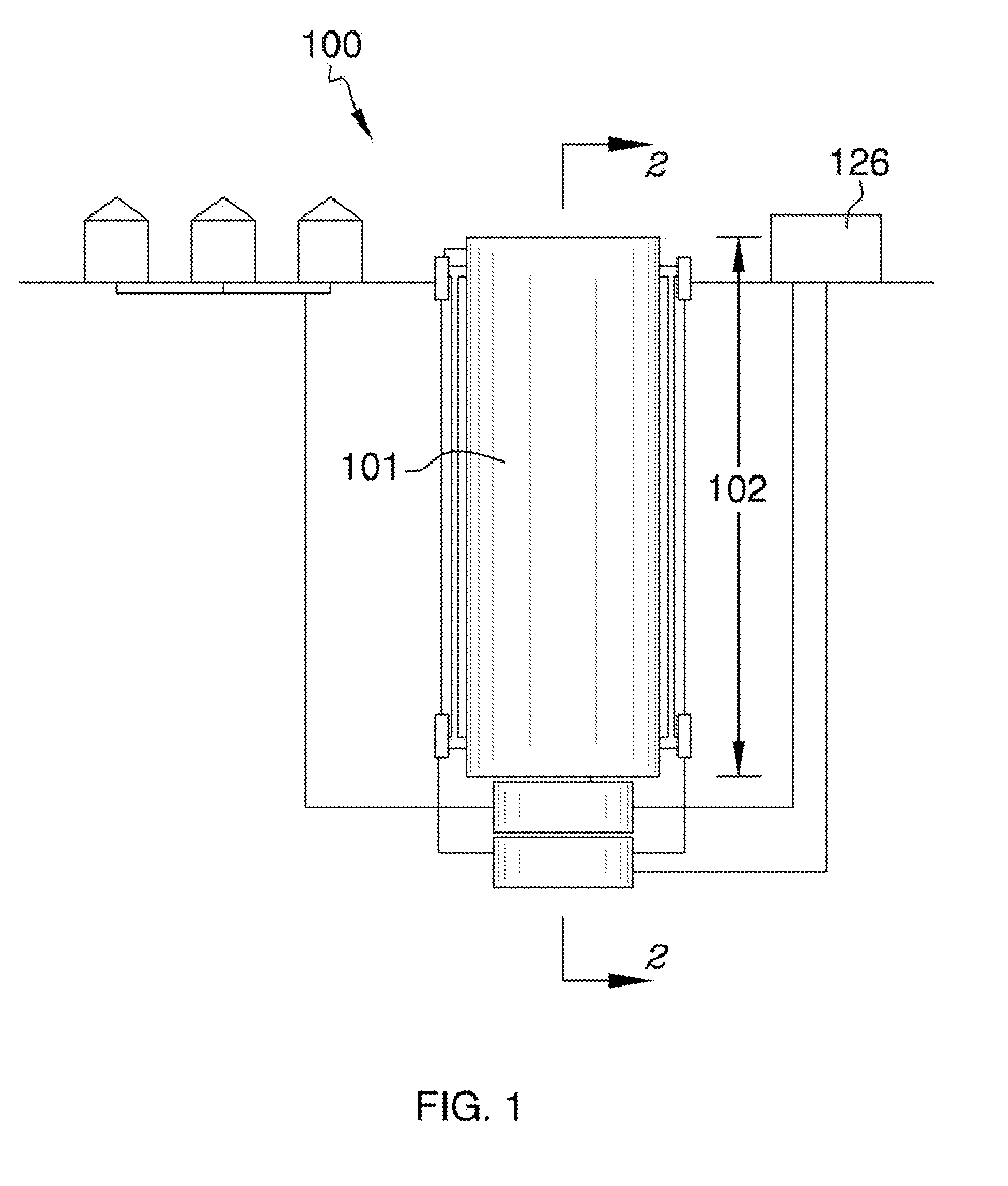
The rail barrel direct energy transferor is a modified rail barrel within which a flywheel consisting of two propellers rotate and traverse back and forth in order to transfer rotational energy to generators provided at distal ends of said rail barrel. The interior of the rail barrel is outfitted with a threaded rod upon which two propellers rotate about and traverse back and forth along. The propellers are adjacent one another and include longitudinal members that extend away from one another. The longitudinal members engage the generators when traversed down the threaded rod in order to transfer the rotational energy. The distal ends include spring pistons that are pushed against when the propellers reach the respective end of the rail barrel. The spring pistons being supplied compressed air from a source, and which pushes the propellers of the flywheel in order to continue the traversing motion.

Description

CROSS REFERENCES TO RELATED APPLICATIONS[0001]This non-provisional utility patent application claims priority to provisional patent application 61 / 501,233, which was filed on Jun. 26, 2011.STATEMENT REGARDING FEDERALLY SPONSORED RESEARCH Not ApplicableREFERENCE TO APPENDIX[0002]Not ApplicableBACKGROUND OF THE INVENTION[0003]A. Field of the Invention[0004]The present invention relates to the field of energy production, conservation, and transference; more specifically, rail barrel that inputs kinetic and potential energy into a flywheel and applicable generators for subsequent release.[0005]B. Discussion of the Prior Art[0006]As will be discussed immediately below, no prior art discloses an electricity production system comprising a rail barrel that includes a generator at distal ends, and within which a threaded rod is extended; wherein a flywheel made of two propellers are provided adjacent one another, and travel collectively up and down the threaded rod; wherein the propellers ea...

Claims


Application Information

Patent Timeline
IPC IPC(8): H02K7/18H02N2/18F03G7/10
CPCH02N2/18H02K35/02H02K7/1876
Inventor CASTOR, VARNELL
Owner CASTOR VARNELL
Learn More