Voltage Controlling Circuit

a voltage control and circuit technology, applied in the direction of limiting amplitude without controlling loop, amplifier with semiconductor devices/discharge tubes, amplifier modifications to reduce noise influence, etc., can solve the problem of introducing noise, affecting the precision of processing output signal vout, and affecting the quality of released audio

Active Publication Date: 2012-12-27
PRINCETON TECHNOLOGY
View PDF5 Cites 2 Cited by
  • Summary
  • Abstract
  • Description
  • Claims
  • Application Information

AI Technical Summary

Benefits of technology

[0008]For neutralizing the noises and peaks in the output signal mentioned in the prior art, the claimed invention discloses a voltage controlling circuit for clamping the voltage level of...

Problems solved by technology

The peaks occurring at the output signal Vout will significantly affect the precision of processing the output signal Vout and introduce noise.
When the input signal is an...

Method used


Image

  • Voltage Controlling Circuit
  • Voltage Controlling Circuit
  • Voltage Controlling Circuit

Examples


Embodiment Construction

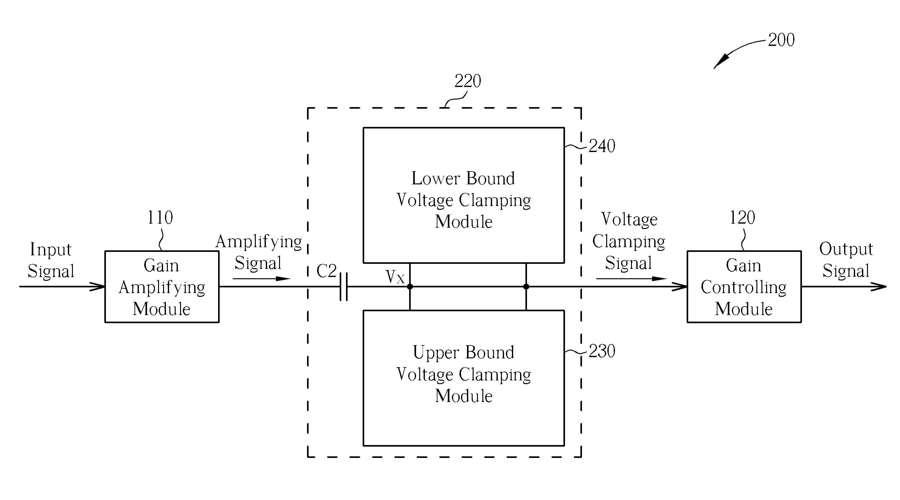
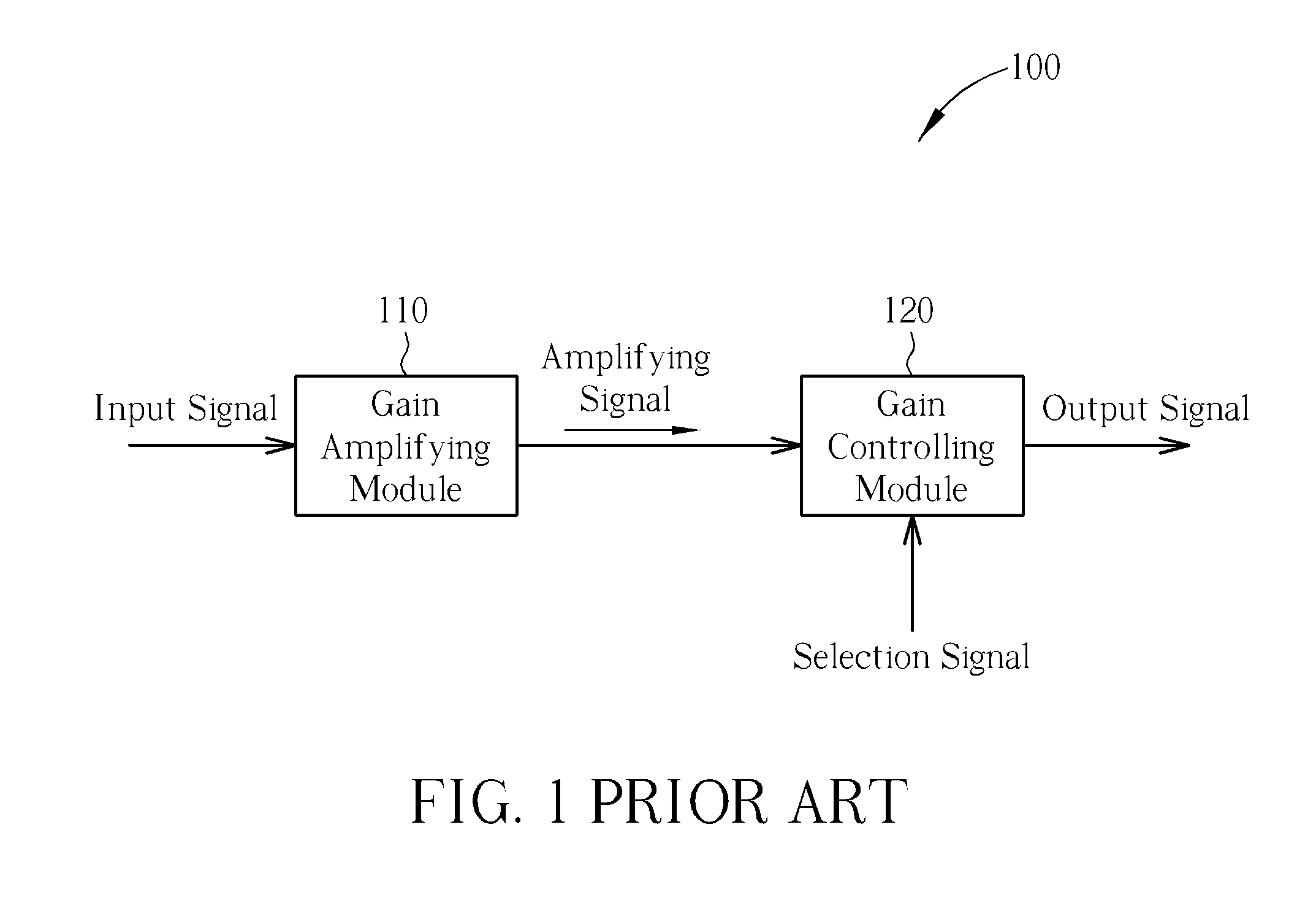
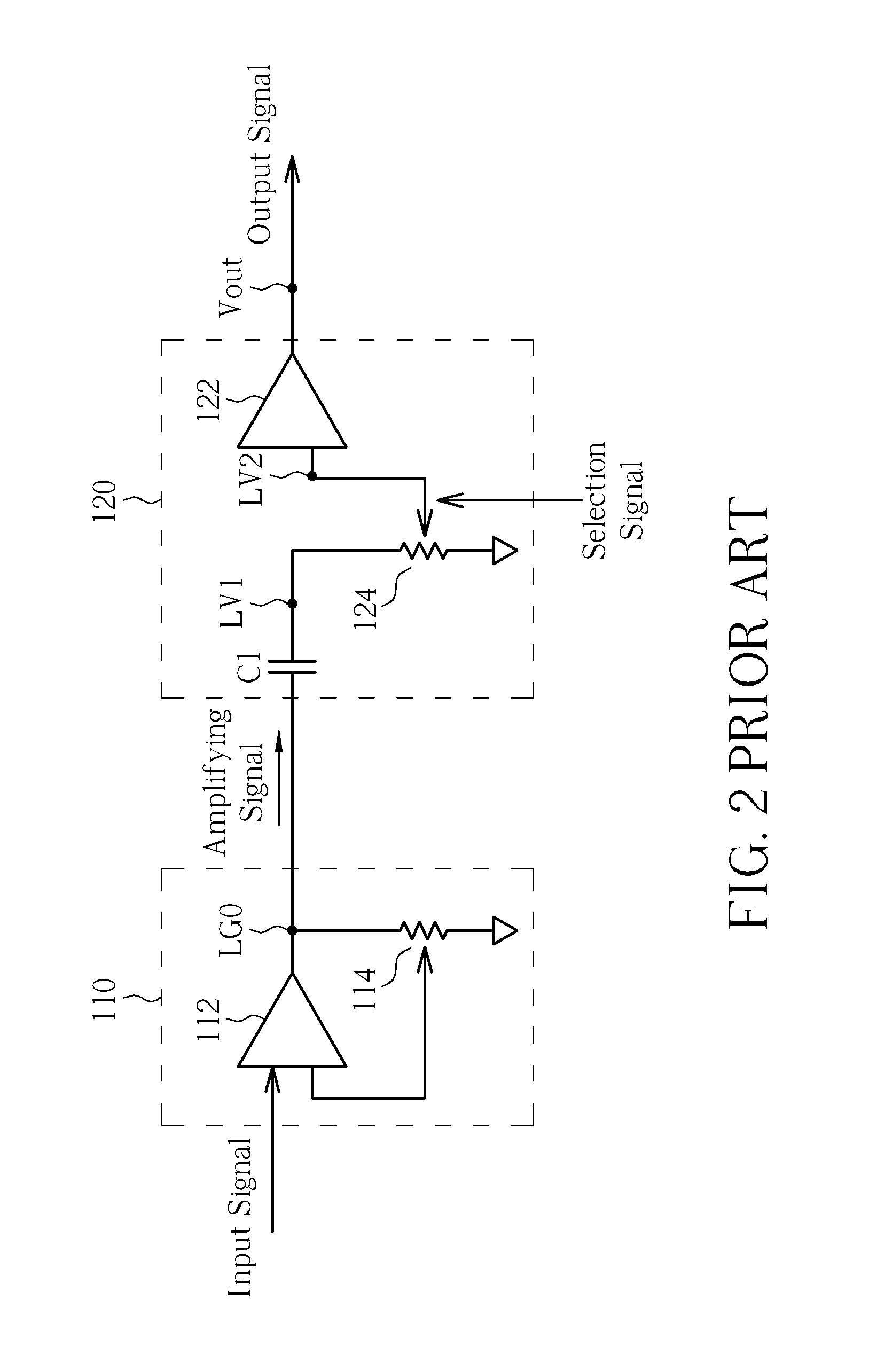
[0018]Please refer to FIG. 5, which is a block diagram of a voltage controlling circuit 200 according to an embodiment of the present invention. As shown in FIG. 5, besides the gain amplifying module 110 and the gain controlling module 120 shown in FIG. 1, the voltage controlling circuit 200 further includes a voltage clamping module 220, which includes a capacitor C2, an upper bound voltage clamping module 230, and a lower bound voltage clamping module 240. The capacitor C2 has the same usage as the capacitor C1 shown in FIG. 2, so the usage of the capacitor C2 is not described again here. The purpose of the voltage clamping module 220 is to clamp the voltage level at a node Vx, which is located at one terminal of the capacitor C2 and corresponds to the node LV1 shown in FIG. 2, within a predetermined range so that the gain controlling module 120 which receives the voltage level at the node Vx will generate the output signal Vout without peaks introduced by the over-charged or over...


PUM


Abstract

A voltage clamping module is disposed at an output terminal of a gain amplifying module, so that a voltage level of an amplifying signal outputted by the gain amplifying module can be clamped within a predetermined range. The voltage clamping module includes an upper bound voltage clamping module, which is utilized for limiting the voltage level of the amplifying signal to be lower than an upper bound voltage level, and a lower bound voltage clamping module, which is utilized for limiting the voltage level of the amplifying signal to be higher than a lower bound voltage level.

Description

BACKGROUND OF THE INVENTION[0001]1. Field of the Invention[0002]The present invention discloses a voltage controlling circuit, and more particularly, a voltage controlling circuit for clamping a voltage level of an amplifying signal within a predetermined range so as to restrain peaks.[0003]2. Description of the Prior Art[0004]Please refer to FIG. 1, which is a block diagram of a conventional analog circuit 100. The analog circuit 100 includes a gain amplifying module 110 and a gain controlling module 120. The gain amplifying module 110 is configured to amplify a gain of an input signal, such as an analog signal, so as to generate an amplifying signal. The gain controlling module 120 is configured to control a gain of the amplifying signal according to an external selection signal so as to generate an output signal, for example, generating the output signal by increasing or decreasing the gain of the amplifying signal by different multiples. The analog circuit 100 shown in FIG. 1 am...

Claims


Application Information

Patent Timeline
IPC IPC(8): H03G3/00
CPCH03F1/26H03F2200/03H03G11/002H03F2200/441H03F2200/411
Inventor LEE, YUNG-MINGHAN, TZU-FEI
Owner PRINCETON TECHNOLOGY
Why Eureka
Try Eureka