Wireless communication system, wireless transmission device and wireless transmission method

a wireless transmission and wireless communication technology, applied in the field of wireless transmission devices and wireless transmission methods, can solve the problems of significant limitations in transmission power and inability to uplink, and achieve the effect of improving cell throughput and throughput of terminal devices

Inactive Publication Date: 2012-12-27
SHARP KK
View PDF5 Cites 11 Cited by
  • Summary
  • Abstract
  • Description
  • Claims
  • Application Information

AI Technical Summary

Benefits of technology

[0034]According to the present invention, it is possible to improve the cell throughput and the throughput for terminal devices.

Problems solved by technology

However, the OFDMA has high PAPR (Peak-to-Average Power Ratio) characteristics, and therefore is not suitable to uplink transmission for which the transmission power is significantly limited.

Method used


Image

  • Wireless communication system, wireless transmission device and wireless transmission method
  • Wireless communication system, wireless transmission device and wireless transmission method
  • Wireless communication system, wireless transmission device and wireless transmission method

Examples


first embodiment

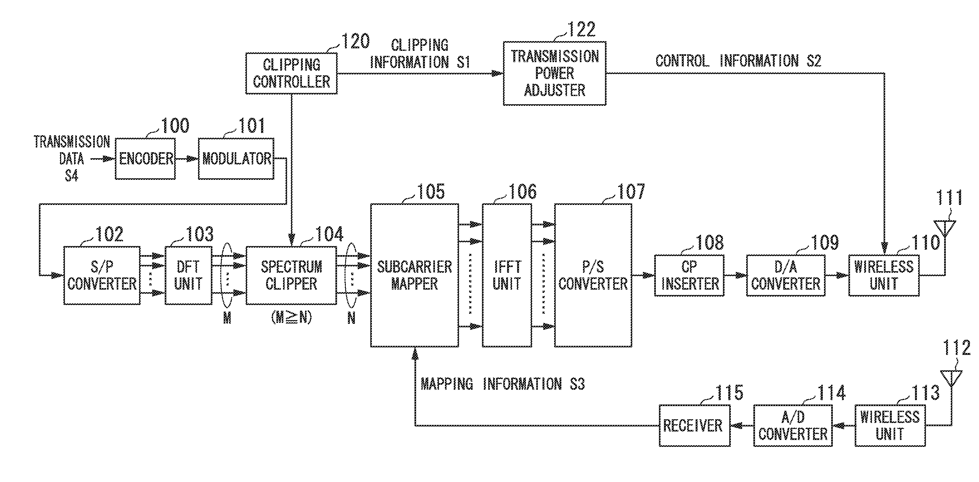
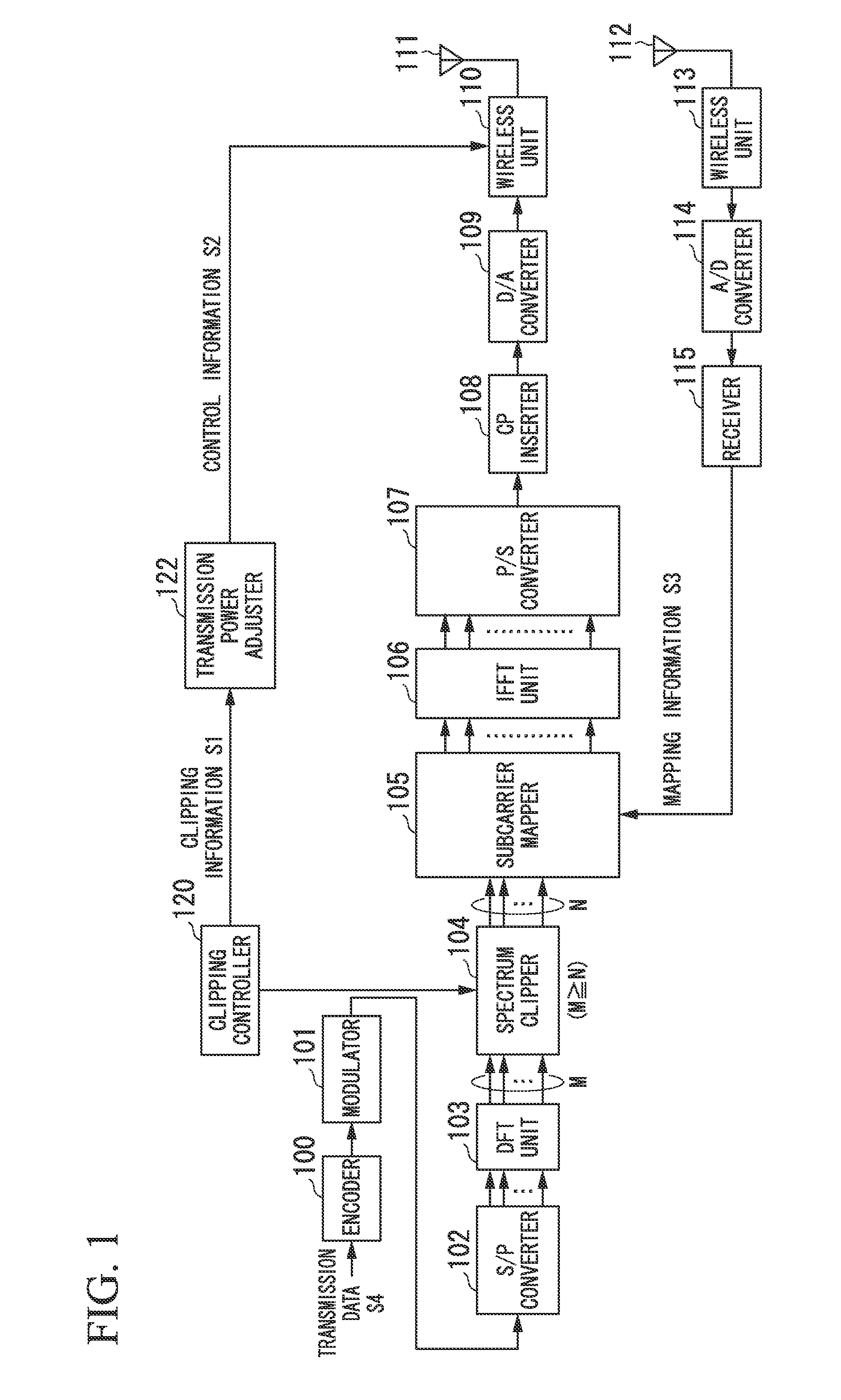
[0058]FIG. 1 is a block diagram illustrating a wireless transmission device according to the present invention. As an example, this wireless communication device is a terminal device that performs transmission to a base station device in a wireless communication system. Hereinafter, a base station device is referred to as a wireless reception device. This wireless transmission device includes: an encoder 100; a modulator 101; an S / P converter 102; a DFT unit 103; a spectrum clipper 104; a subcarrier mapper 105; an IFFT unit 106; a P / S converter 107; a CP inserter 108; a D / A converter 109; a wireless unit 110; a transmission antenna unit 111; a reception antenna unit 112; a wireless unit 113; an A / D converter 114; a receiver 115; a clipping controller 120; and a transmission power adjuster 122.

[0059]The encoder 100 receives transmission data S4, performs error correction coding on the received transmission data S4, and outputs to the modulator 101, the transmission data subjected to ...

second embodiment

[0087]In the second embodiment, with reference to a method described in specifications of the next generation cellular communication (3.9G), particularly, a method using the relationship between transmission power control and clipping is explained under an assumption that the clipped DFT-S-OFDM is used for an uplink. For 3.9G, it has been determined to use the SC-FDMA. Formula (1) is a formula used to determine a transmission power value to be used for uplink data communication defined in a specification of the next generation cellular communication (3.9G).

PPUSCH(i)=min {PCMAX, 10×log10(MPUSCH(i))+PO—PUSCH(j)+α(j)×PL+ΔTF(i)+f(i)}  (1)

[0088]In formula (1), PUSCH is an abbreviation of a physical uplink shared channel, and denotes a data channel for transmitting uplink data. PPUSCH(i) denotes a transmission power value for the i-th frame. j denotes a parameter determined according to a method of assigning frequencies to be used. A value of j differs among a case where assignment of fre...

third embodiment

[0102]In the third embodiment, a method of improving the cell throughput and the throughput for terminal devices by effectively using the clipped DFT-S-OFDM for an uplink in the cellular system is explained.

[0103]FIG. 5A is a diagram illustrating the position relationship between wireless transmission devices (terminal devices) 201 to 203 which transmit clipped DFT-S-OFDM signals and a wireless reception device (base station device) 210 which are included in a cellular system. It is assumed in the case of FIG. 5A that the farthest terminal device from the base station device 210 is the terminal device A (201), followed by the terminal device B (202) and the terminal device C (203) in this order. An ellipse 220 denotes a service coverage area in which the wireless base station device can communicate with the terminal devices. FIG. 6 is a diagram illustrating the relationship between each terminal device and a non-clipping rate according to the third embodiment.

[0104]As shown in FIGS....


PUM


Abstract

A wireless communication system includes: wireless transmission devices; and a wireless reception device. Each of the wireless transmission devices is configured to transmit data by transforming a time domain signal into frequency domain signals to obtain first frequency signals, clipping a part of the first frequency signals to generate second frequency signals, and allocating the second frequency signals onto subcarriers. The wireless reception device is configured to demodulate, from signals received, time domain data transmitted. Communication is performed using a clipping rate set for each of the wireless transmission devices, the clipping rate being the number of the second frequency signals divided by the number of the first frequency signals.

Description

TECHNICAL FIELD[0001]The present invention relates to a wireless communication system, a wireless transmission device and a wireless transmission method.[0002]Priority is claimed on Japanese Patent Application No. 2010-043095, filed Feb. 26, 2010, the content of which is incorporated herein by reference.BACKGROUND ART[0003]Along with the recent increase in the amount of data communication, the need for mobile communication systems with higher frequency use efficiency has been increasing. Various considerations regarding single-cell reuse cellular systems are in progress. The standardization of an E-UTRA (Evolved Universal Terrestrial Radio Access) system, which is one of the single-cell reuse cellular systems, has been considered primarily by 3GPP (3rd Generation Partnership Project). Regarding the E-UTRA system, OFDMA (Orthogonal Frequency Division Multiple Access) has been considered as one of prospective downlink transmission schemes. Additionally, non-contiguous / contiguous DFT-S...

Claims


Application Information

Patent Timeline
Patent Type & Authority Applications(United States)
IPC IPC(8): H04W52/02H04W52/04H04W72/04
CPCH04J11/003H04L5/0007H04L5/0016H04L5/0023H04L2025/03414H04L5/0046H04L25/03159H04L25/03171H04L27/2614H04L5/0039
Inventor HAMAGUCHI, YASUHIROYOKOMAKURA, KAZUNARINAKAMURA, OSAMUGOTO, JUNGOTAKAHASHI, HIROKITO, SHIMPEI
Owner SHARP KK
Why Eureka
Try Eureka