

System and method of integrated battery charging and balancing
a technology of integrated battery charging and balancing, applied in the field of batteries, can solve problems such as system insufficientness
Inactive Publication Date: 2013-01-03
PANACIS
View PDF2 Cites 29 Cited by
- Summary
- Abstract
- Description
- Claims
- Application Information
AI Technical Summary
Benefits of technology
The technical effects of this patent are an integrated system that can charge and balance cells simultaneously, using a voltage regulated power converter and a transformer with multiple windings. Each cell can charge to the same voltage as the others, and the system can charge quickly either by directing energy into a series string of cells or by using a bulk energy source. This solution helps to achieve the highest overall charging rate while balancing cells.
Problems solved by technology
However, at higher current and higher imbalance levels, these systems may not suffice as they only have the ability to transfer energy between two cells.
Method used
View moreImage
Smart ImageViewing Examples

Examples
Login to View More PUM
 Abstract
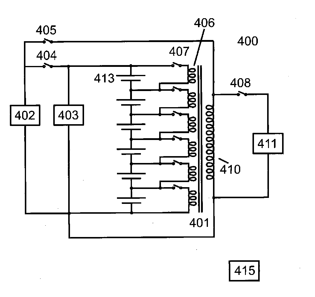
A system and method is provided that allows the cells making up a battery pack to be kept at equal energy storage levels through the use of active re-distribution of the energy in each cell through a bi-directional transformer coupling means that will allow balancing to occur during charging, discharging, bulk charging, parallel charging or idle states.
Description
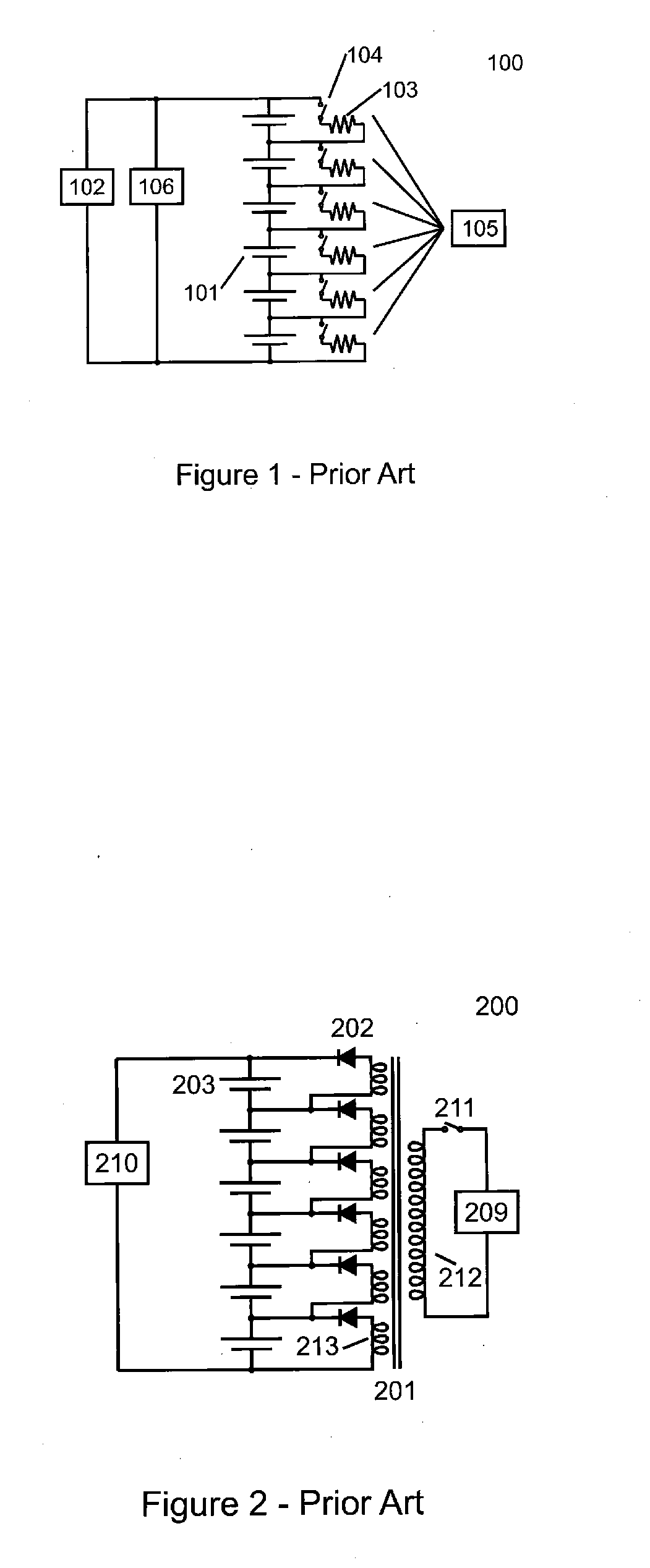
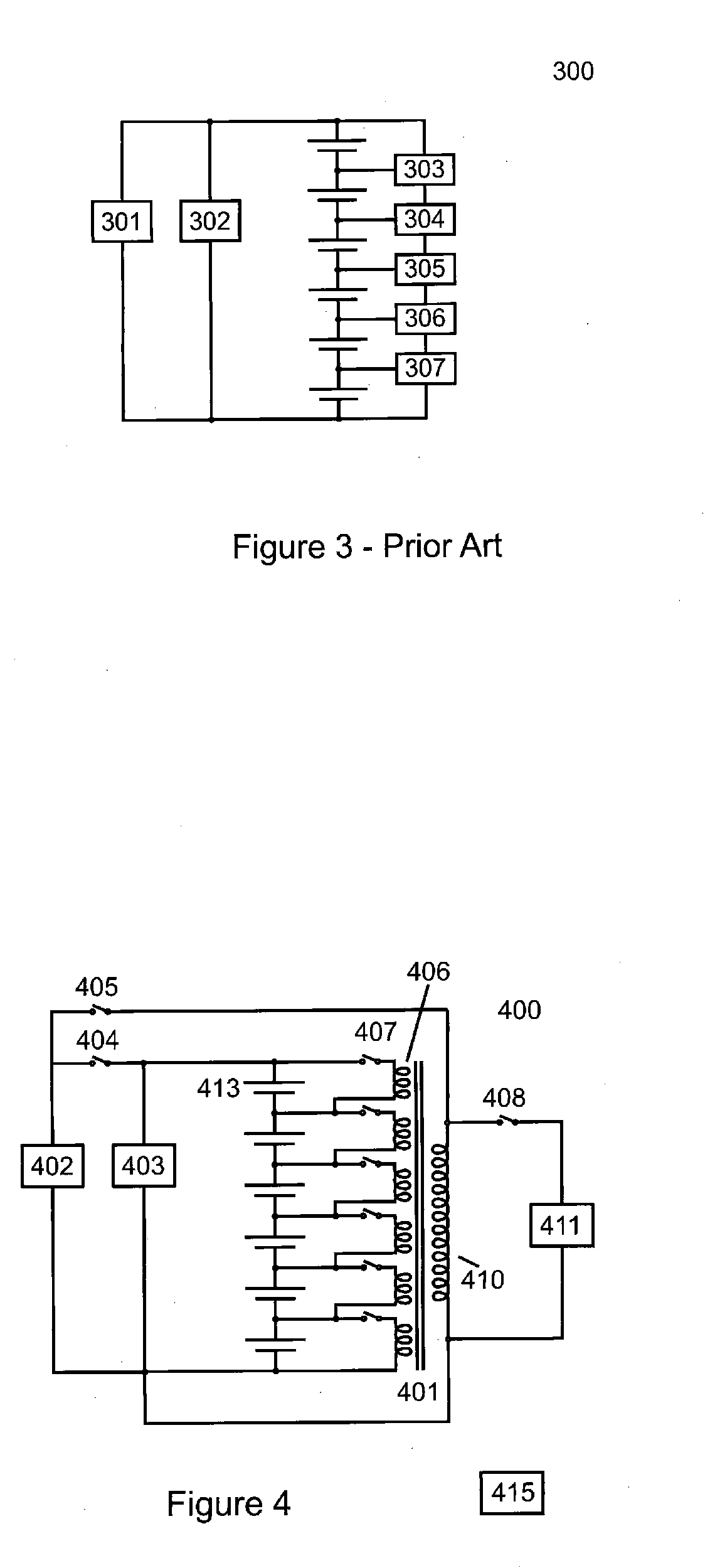
TECHNICAL FIELD[0001]This invention pertains to the field of batteries, and particularly to the methods used to maintain and control the individual cells that make up a battery by the application of charging, charge balancing and discharge balancing energy.BACKGROUND ART[0002]It is well understood that modern battery technologies have significant safety issues related to the energy stored within them. Many modern technologies such as lithium based chemistries, are very sensitive to overcharging or over discharging. It is therefore desirable to implement a system that maintains each cell in a given battery pack at the same state of charge. As the cells in a battery pack wear out, their capacities tend to drift apart.[0003]Conventional balancing technologies focus only on the individual cell voltages at the end of charging. A number of active and passive cell balancing techniques have been proposed that ensure each cell in a battery pack ends up fully charged at about the same voltage...
Claims
Login to View More Application Information
Patent Timeline
 Patent Type & AuthorityApplications(United States)
IPC IPC(8): H02J7/00
CPCH02J7/0016
InventorBODKIN, RICHARDLUKSO, RICHARD
OwnerPANACIS