
Battery structures

a battery and wire technology, applied in the field of batteries, can solve the problems of limited material types, increasing energy requirements, and limited use of wires, and achieve the effects of increasing battery power, maintaining current use times, and long use tim

Inactive Publication Date: 2015-05-21
TRION ENERGY SOLUTIONS CORP
View PDF2 Cites 2 Cited by
  • Summary
  • Abstract
  • Description
  • Claims
  • Application Information

AI Technical Summary

Benefits of technology

The patent text explains a solution for improving the performance of batteries in portable devices. By increasing the cross-sectional area of the conductor, the resistance of the battery is reduced, allowing for larger amounts of current to be carried. However, this solution becomes problematic when replacing batteries with higher capacity and faster charging rates within the existing battery form factors of countless portable batteries. The patent proposes the creation of adaptive battery mounting cages that can securely hold standard form factor batteries and be easily removed without the need for tools. These cages can be attached to the existing mounting hardware for the traditional battery. The technical effect of this solution is to improve the performance of batteries in portable devices while maintaining the existing form factors for the batteries.

Problems solved by technology

Unfortunately, while these devices have become exponentially more powerful and, as a result, require an increasing amount of energy to run, there have been very little corresponding advancements in battery technology.
The use of these wires has limited the type of materials that can be utilized for the cathode and anode.
Furthermore, since the wires are attached at a single point, they can bottleneck the chemical reaction involved in recharging or discharging a battery.
Again, in traditional batteries this has been accomplished by connecting battery plates internally via single-point solder joints or conductive-element-filled epoxies to a plurality of wires which limits the type of materials that can be utilized for the cathode and anode and creates a bottleneck with respect to the chemical reaction involved in recharging or discharging a battery.
Despite the popularity of today's lithium-ion batteries, they do have several important limitations including:(1) Being prone to thermal runaway and catching fire.
In an attempt to prevent or minimize damage from this problem, some lithium-ion batteries have been placed within metal encasements, often with coolant added, which adds weight and cost to the battery.
Not only does this decrease the usable energy storage of the battery, but this monitoring also increases the battery's cost when monitoring, connections and circuit boards are incorporated to maintain the battery charge within these ranges.(2) While lithium-ion batteries are less prone to the memory effect than say nickel cadmium, they still are only rated to up to approximately 1,200 charge / discharge cycles.
This is especially troublesome for use in items that are frequently being recharged such as electric cars, laptops, mission critical military applications and smartphones.(3) Lithium is a relatively rare element and is expensive.
Furthermore, lithium batteries are toxic and are expensive to dispose of properly as hazardous waste.(4) High capacity lithium batteries take hours to fully charge due to the need of a second phase cycle.
While other materials have shown promise in replacing lithium based batteries, current battery structures limit their applicability.
For example, the fact that battery cells have traditionally seen connected internally via single-point solder joints or conductive-element-filled epoxies to a plurality of wires has limited the use of some alternative materials.

Method used


Image

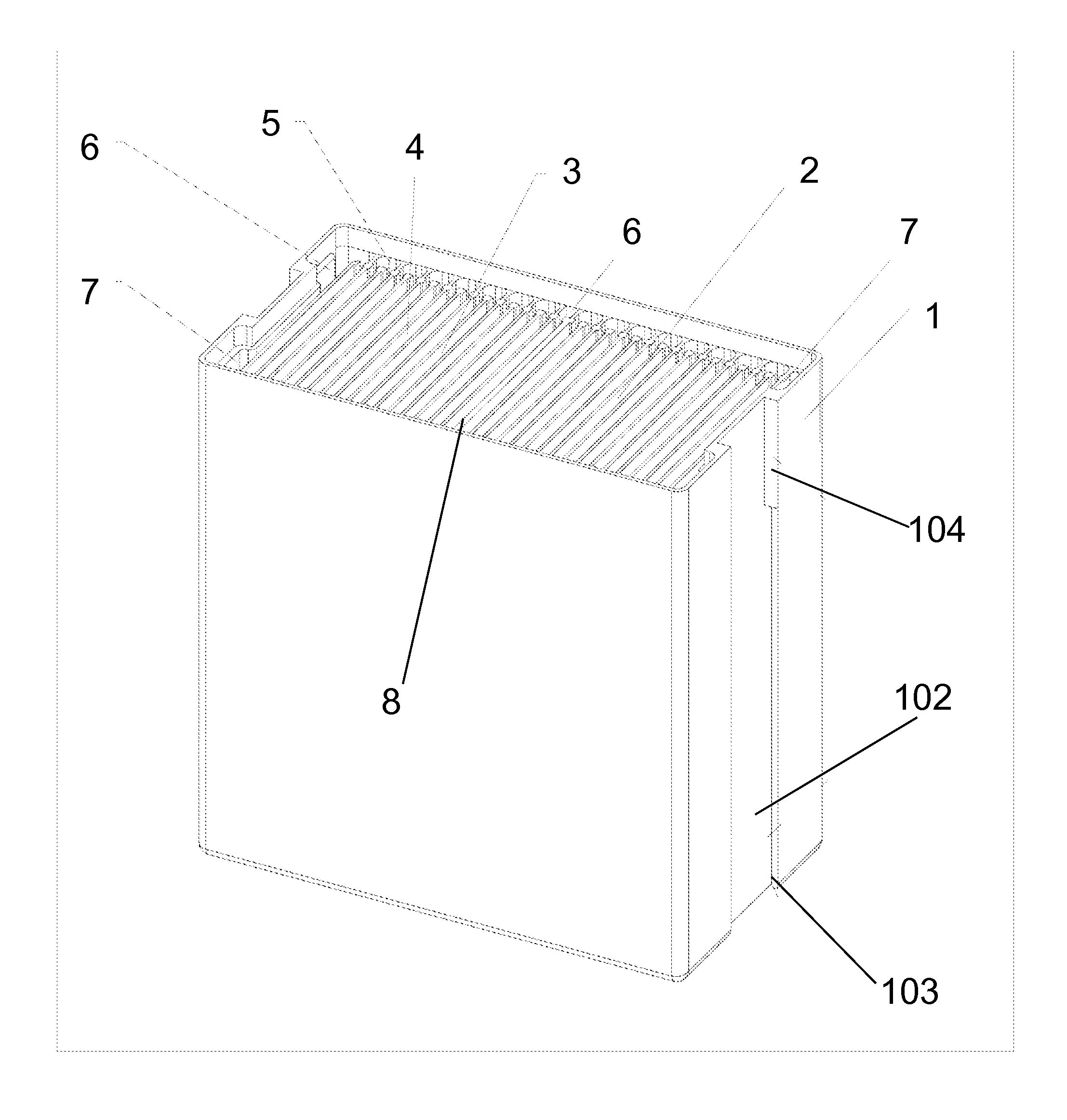
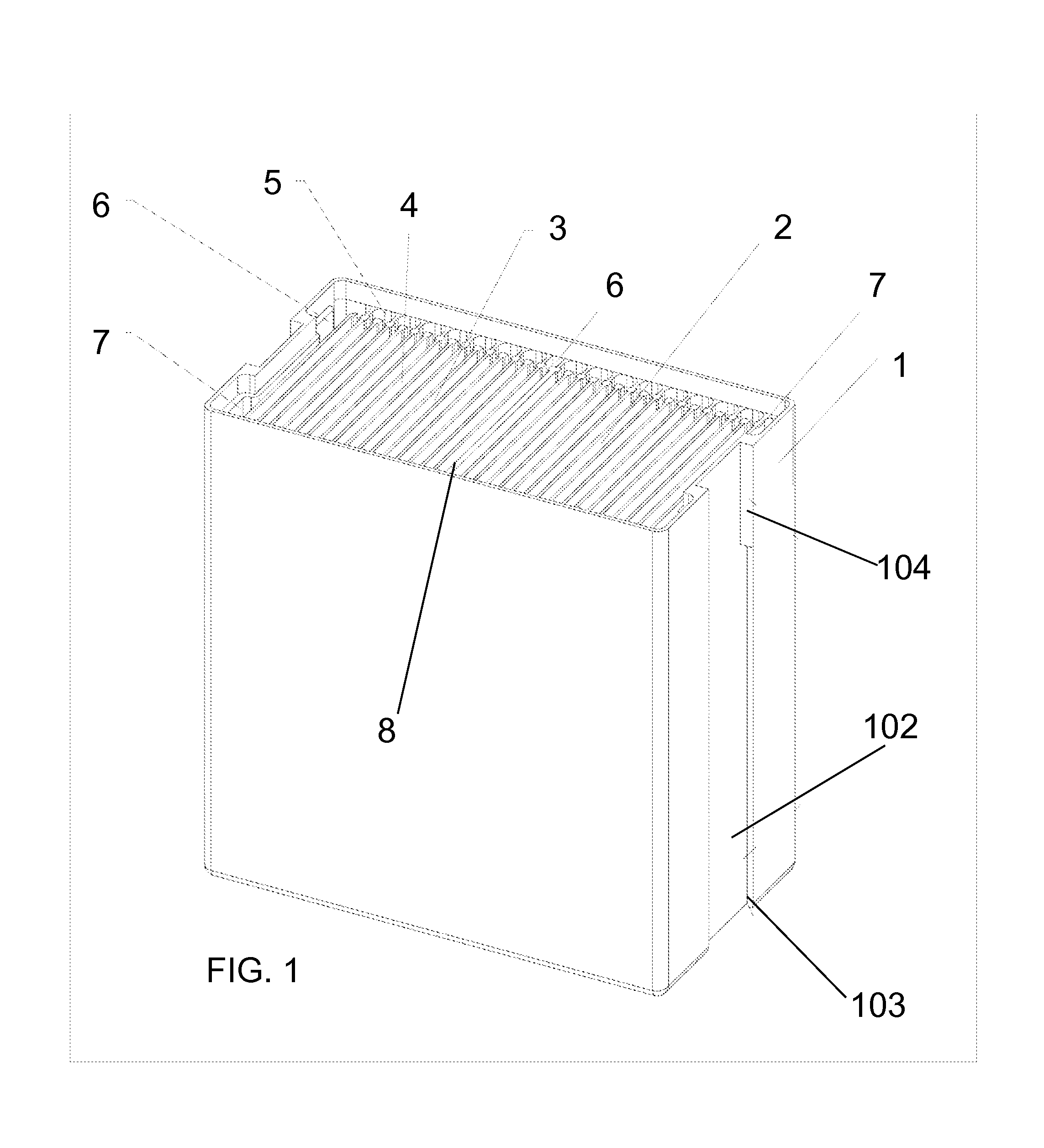
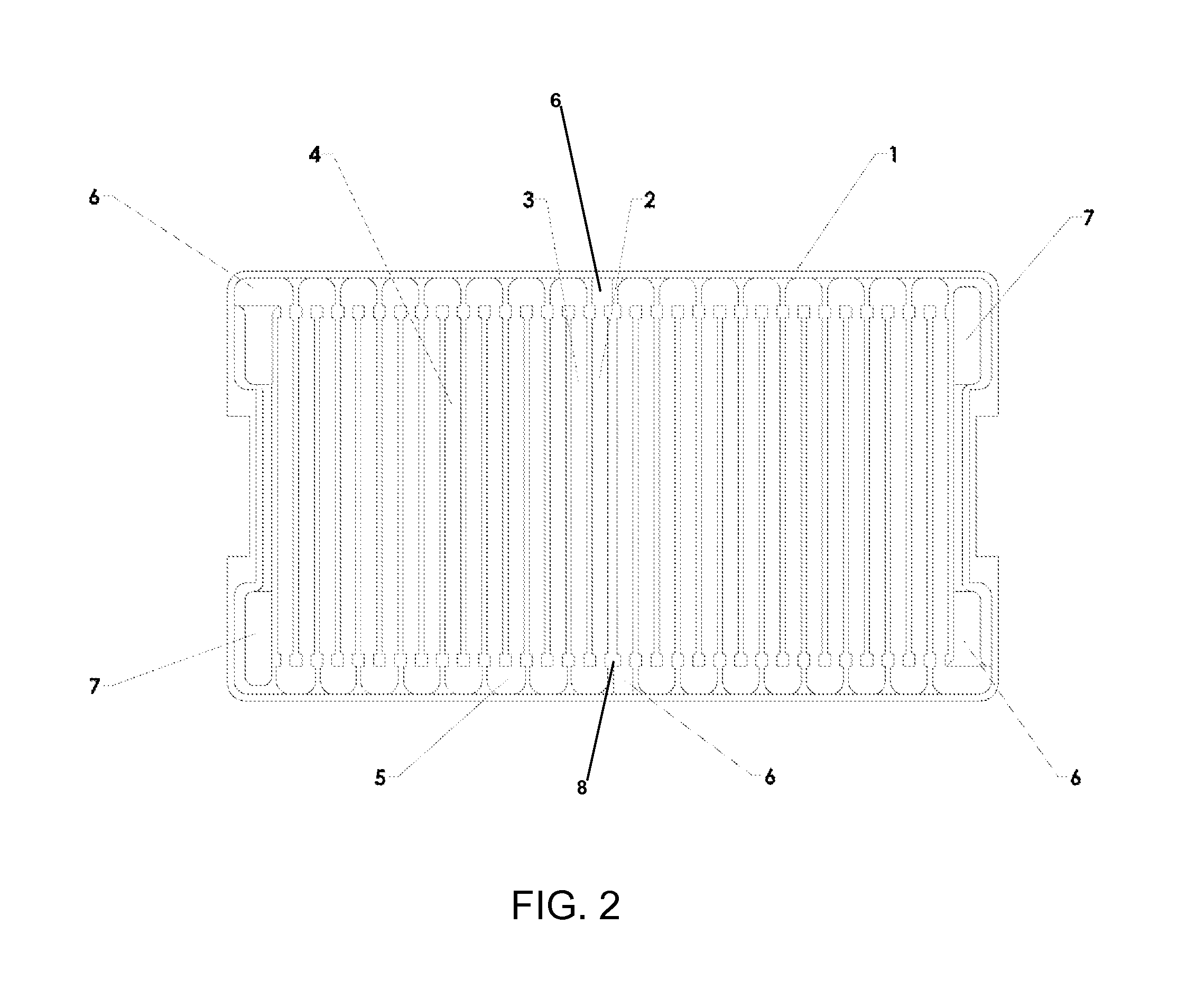
  • Battery structures
  • Battery structures
  • Battery structures

Examples


Embodiment Construction

Synopsis of the Detailed Description

[0037]It is believed that recent improvements and developments in battery chemistry have led to materials that can increase energy storage capacity anywhere from three times up to a theoretical ten times that of the today's best Lithium-ion batteries. The chemistry also allows for far more rapid battery charge times as well. However, some limitations of implementing this new chemistry into current batteries are the conductive limitations of the internal / external wiring, the single-point connections to the internal battery plates, and the surface areas of the connector pins / flats.

[0038]The larger the cross-sectional area of the conductor, the more electrons per unit length are available to carry the current, and, as a result, the resistance is lower in larger cross-section conductors. A common approach to enabling greater current loads is to increase the wire diameter (gauge). However, this solution becomes problematic when replacing batteries with...


PUM


Abstract

Battery structures are formed such that the use of wires and soldering is eliminated or reduced. The battery plates can be infused down their anode and the cathode edges with an electrically conductive epoxy or sealant that connects said plates to each other and takes the place of traditional copper wires. Additional connection channels, including those in the top structure, can be filled with electrically conductive materials to replace wires and make the necessary connections. The battery structures can be configured to create a dual voltage battery. The insertion of the battery plates is easily configured within the assembly process to achieve a variety of in-series or in-parallel connections thus varying the voltage and amperage to achieve a desired output, all within the same enclosure.

Description

CROSS-REFERENCES TO RELATED APPLICATIONS[0001]This application claims priority to and benefits from U.S. provisional patent application Ser. No. 61 / 892,400 filed Oct. 17, 2013. This application also claims priority to and benefits from U.S. provisional patent application Ser. No. 61 / 892,401 filed Oct. 17, 2013. This application also claims priority to and benefits from U.S. provisional patent application Ser. No. 61 / 940,791 filed Feb. 17, 2014. The '400, '401, and '791 provisional applications are expressly incorporated herein by reference in their entirety.FIELD OF THE INVENTION[0002]The present invention relates to batteries and, in particular, to battery structures that eliminate or reduce the need for solder joints and wires for internal electrical connections. The invention also relates to the creation of non-lithium-ion batteries; though battery chemistries using lithium ions can benefit from this approach as well. In some embodiments, additive manufacturing is used to create ...

Claims


Application Information

Patent Timeline
IPC IPC(8): H01M2/22H01M10/38H01M2/04H01M10/48H01M2/12H01M50/112H01M50/147H01M50/528H01M50/54H01M50/552
CPCH01M2/22H01M10/48H01M2/1264H01M10/488H01M2220/20H01M2/0404H01M2/043H01M10/38H01M2220/30H01M2/04Y02E60/10H01M50/112H01M50/147H01M50/528H01M50/54Y02P70/50H01M50/552H01M50/394
Inventor WATERFORD, STEVEZWASKA, THOMAS R.
Owner TRION ENERGY SOLUTIONS CORP
Learn More