Charging rate leveling device and power supply system

a charging rate and power supply system technology, applied in secondary cell servicing/maintenance, electrochemical generators, instruments, etc., can solve the problem of actual depletion of battery module whole capacity in conformity with battery cell, and achieve the effect of reducing the difference between charging rates, reducing transferring operations, and large electric charges

Active Publication Date: 2020-05-19
YAZAKI CORP
View PDF22 Cites 2 Cited by
  • Summary
  • Abstract
  • Description
  • Claims
  • Application Information

AI Technical Summary

Benefits of technology

[0015]Since the charging rate leveling device further includes: an auxiliary battery charge connected to the auxiliary battery; a discharging connection selector capable of selectively connecting each of the plurality of battery cells to the auxiliary battery charger, so as to charge the auxiliary battery with electric power of the battery cell, wherein the connection selection controller further controls the charging connection selector to connect one battery cell selected from the plurality of battery cells to the auxiliary battery charger so as to reduce the difference between charging rates of each of the plurality of battery cells, the battery cell of which charging rate is relatively high is connected to the auxiliary battery charger for example, it is possible to charge the auxiliary battery capable of charging relatively larger electric charge with the electric power of the battery cell, namely, to transfer electric charge. Because one transferring operation thus allows for transferring large electric charge, it is possible to reduce transferring operation of the electric charge, and quickly leveling each charging rate of the plurality of battery cells the battery pack includes.
[0015]Since the charging rate leveling device further includes: an auxiliary battery charge connected to the auxiliary battery; a discharging connection selector capable of selectively connecting each of the plurality of battery cells to the auxiliary battery charger, so as to charge the auxiliary battery with electric power of the battery cell, wherein the connection selection controller further controls the charging connection selector to connect one battery cell selected from the plurality of battery cells to the auxiliary battery charger so as to reduce the difference between charging rates of each of the plurality of battery cells, the battery cell of which charging rate is relatively high is connected to the auxiliary battery charger for example, it is possible to charge the auxiliary battery capable of charging relatively larger electric charge with the electric power of the battery cell, namely, to transfer electric charge. Because one transferring operation thus allows for transferring large electric charge, it is possible to reduce transferring operation of the electric charge, and quickly leveling each charging rate of the plurality of battery cells the battery pack includes.
[0016]Since the charging rate leveling device includes: a battery cell detector detecting a highest voltage battery cell and a lowest voltage battery cell, the highest voltage battery cell having a highest voltage between both electrodes and the lowest voltage battery cell having a lowest voltage between both electrodes, among the plurality of battery cells; a charging rate detector detecting a charging rate of the highest voltage battery cell and a charging rate of the lowest voltage battery cell, wherein the connection selector controller, when at least one of the charging rate of the highest voltage battery cell and the charging rate of the lowest voltage battery cell falls out of a range of a reference charging rate and a difference value between the charging rates exceeds a difference upper limit value, controls the discharging connection selector to connect the highest voltage battery cell to the auxiliary battery charger, and controls the charging connection selector to connect the lowest voltage battery cell to the battery cell charger, the highest voltage battery cell and the lowest voltage battery cell are thought to be large in difference in charging rate from the other battery cell, and it is possible to transfer electric charge therebetween via the auxiliary battery, allowing for more quickly leveling each of charging rate of the plurality of battery cells the battery pack includes.
[0017]The battery cell detector includes one voltage detector, and voltage detecting connection selector able to electively connect the voltage detector to each of the plurality of battery cells, the voltage detecting connection selector is configured to serve as the discharge connection selector by enabling each of the plurality of battery cells to selectively connect to the auxiliary battery charger as well, and thereby part composing the connection selector can be reduced and production cost can also be reduced.
[0018]The lowest voltage battery cell of the voltage between both electrodes of which voltage between both electrodes is lowest is supposed to be large in the difference in the charging rate from the other battery cells. Thus, a battery cell detector detecting a highest voltage battery cell and a lowest voltage battery cell, the highest voltage battery cell having a highest voltage between both electrodes and the lowest voltage battery cell having a lowest voltage between both electrodes, among the plurality of battery cells; a charging rate detector detecting a charging rate of the highest voltage battery cell and a charging rate of the lowest voltage battery cell, wherein the connection selector controller, when a difference value between the charging rate of the highest voltage battery cell and the charging rate of the lowest voltage battery cell exceeds a difference upper limit value, controls the charging connection selector to connect the lowest voltage battery cell to the battery cell charger, it is possible to transfer charge from the auxiliary battery to the lowest voltage battery cell, and to more quickly level each of charging rate of the battery cells the battery pack includes.
[0019]According to the second aspect of the present invention, since the charging rate leveling device is composed of any above mentioned charging rate leveling device, for example, connection of the battery cell of which charging rate is relatively small to the battery cell charger so as to charge the concerned battery cell with the auxiliary battery capable of storing relatively large electric charge, namely, electric charge can be transferred so as to reduce the difference of each of the charging rate of the plurality of battery cells. Therefore, because of allowing for transfer of large electric charge at one transferring operation, it is possible to reduce transferring operation of electric charge, allowing for each of leveling charging rate of the plurality of battery cells the battery charge includes.

Problems solved by technology

Because charge or discharge of the battery module is made in conformity with degraded battery cells, the other battery cells not degraded cannot be fully consumed, resulting in actual decrease of whole capacity of battery module in conformity with the battery cell degraded.

Method used


Image

  • Charging rate leveling device and power supply system
  • Charging rate leveling device and power supply system
  • Charging rate leveling device and power supply system

Examples


first embodiment

[0028]Hereinafter, regarding a charging rate leveling device of the first embodiment of the present invention and a power supply system including the same will be explained with reference to FIGS. 1 to 5.

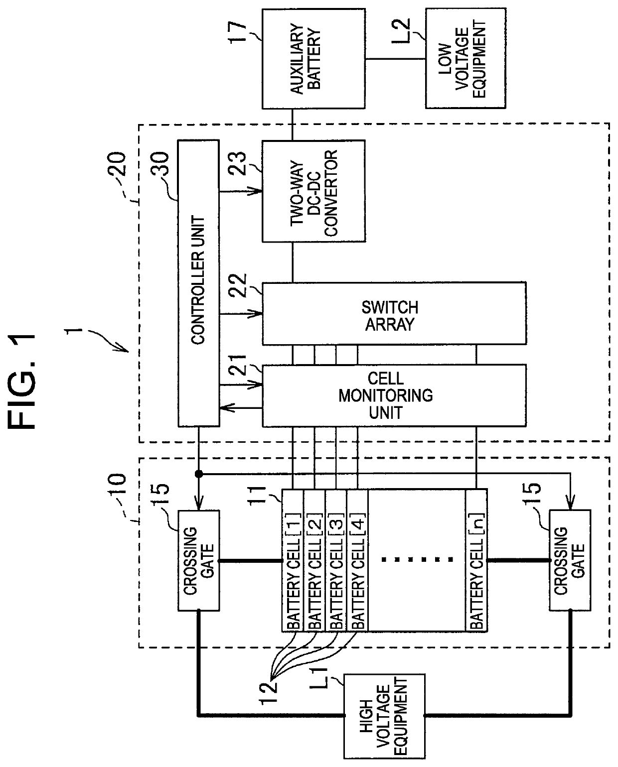
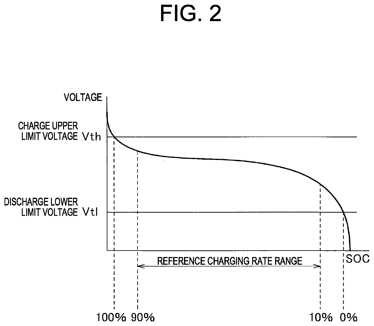
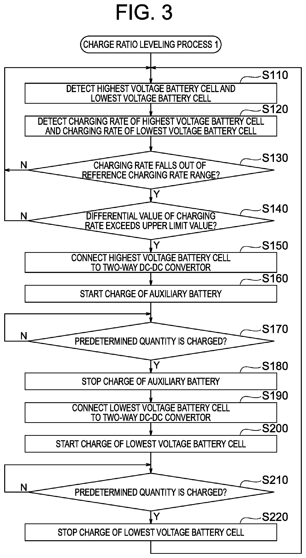
[0029]FIG. 1 is a view illustrating a schematic configuration of a power supply system of the first embodiment of the present invention. FIG. 2 is a view schematically illustrating relationship between a voltage between both electrodes of a battery cell a battery pack of the power supply system in FIG. 1 includes and a charging rate. FIG. 3 is a flowchart illustrating one example of charging rate leveling process 1 a controller of control device of the power supply system in FIG. 1 performs. FIG. 4 is a view schematically illustrating transferring electric charge from the battery cell to the auxiliary battery in the power supply system in FIG. 1. FIG. 4 is a view schematically illustrating transferring of electric charge from a battery cell to the auxiliary battery in the power supp...

second embodiment

[0071]Hereinafter with reference to FIGS. 6 to 8, a charging rate leveling device of the second embodiment and a power supply system including the same will be described.

[0072]FIG. 6 schematically illustrates a configuration of the power supply system of the second embodiment of the present invention. FIG. 7 is the flowchart illustrating one example of a charging rate leveling process 2 the controller of the control device of the power supply system in FIG. 6 executes. FIG. 8 is a view schematically illustrating transferring charge from the auxiliary battery to battery cell in the power supply system in FIG. 6.

[0073]The power supply system of the present embodiment, as similar to the power supply system of the abovementioned first embodiment, for example, is mounted in a vehicle such as electric vehicle, supplies electric power to a high voltage equipment such as electric motor of the vehicle, levels charging rate of the plurality of battery cells the battery pack of the power suppl...


PUM

PropertyMeasurementUnit
voltageaaaaaaaaaa
voltageaaaaaaaaaa
currentaaaaaaaaaa

Abstract

Provided are a charging rate leveling device and a power supply system including the charging rate leveling device capable of leveling more quickly a charging rate of a plurality of battery cells a battery pack includes. In the power supply system a controlling device includes a two-way DC / DC convertor connected to an auxiliary battery separated from the battery pack, a switch array capable of selectively connecting each of the plurality of auxiliary battery cells the battery pack includes to the two-way DC / DC convertor, so as to charge the battery cell with electric power of the auxiliary battery, and a controller controlling the switch array to connect the lowest voltage battery cell selected among the plurality of battery cells, so as to reduce a difference between charging rates SOC of each of the plurality of battery cells.

Description

FIELD OF THE INVENTION[0001]The present invention is related to a charging rate leveling device leveling a charging rate of a plurality of cells a battery pack includes and a power supply system having the same.DESCRIPTION OF THE RELATED ART[0002]In various vehicles such as an electric vehicle (EV) running with an electric motor, or a hybrid electric vehicle (HEV) running together with an engine and an electric motor, mounted as a power source for electric motor is a battery module including a battery pack having a plurality of battery cells (unit cell) composed of a secondary battery such as lithium ion battery or nickel hydride battery.[0003]Since a large electric power is required for operating such electric motor, a plurality of battery cells is connected in series in order to output high voltage in the battery module. For the plurality of such battery cells of the battery module, resulting from individual difference or deviation of circumferential temperature, a part battery ce...

Claims


Application Information

Patent Timeline
Patent Type & Authority Patents(United States)
IPC IPC(8): H02J7/00H02J7/34H01M10/48H01M10/44G01R31/3835
CPCH01M10/48H01M10/482H02J7/0019H02J7/0016H02J7/342H01M10/441H02J7/0047G01R31/3835Y02T10/7055Y02T10/70Y02E60/10H02J7/0048H02J7/005
Inventor SYOUDA, TAKAHIRO
Owner YAZAKI CORP
Why Eureka
Try Eureka