Electromagnetically actuated microshutter

Inactive Publication Date: 2013-01-03
GOOGLE LLC
View PDF1 Cites 12 Cited by
  • Summary
  • Abstract
  • Description
  • Claims
  • Application Information

AI Technical Summary

Benefits of technology

[0019]An object of an embodiment of the present invention

Problems solved by technology

A disadvantage of micro-mirror structures of the type described in relation to FIGS. 1 and 2 lies in the size associated with the placement of magnets 25 and 27.
A disadvan

Method used


Image

  • Electromagnetically actuated microshutter
  • Electromagnetically actuated microshutter
  • Electromagnetically actuated microshutter

Examples


Example

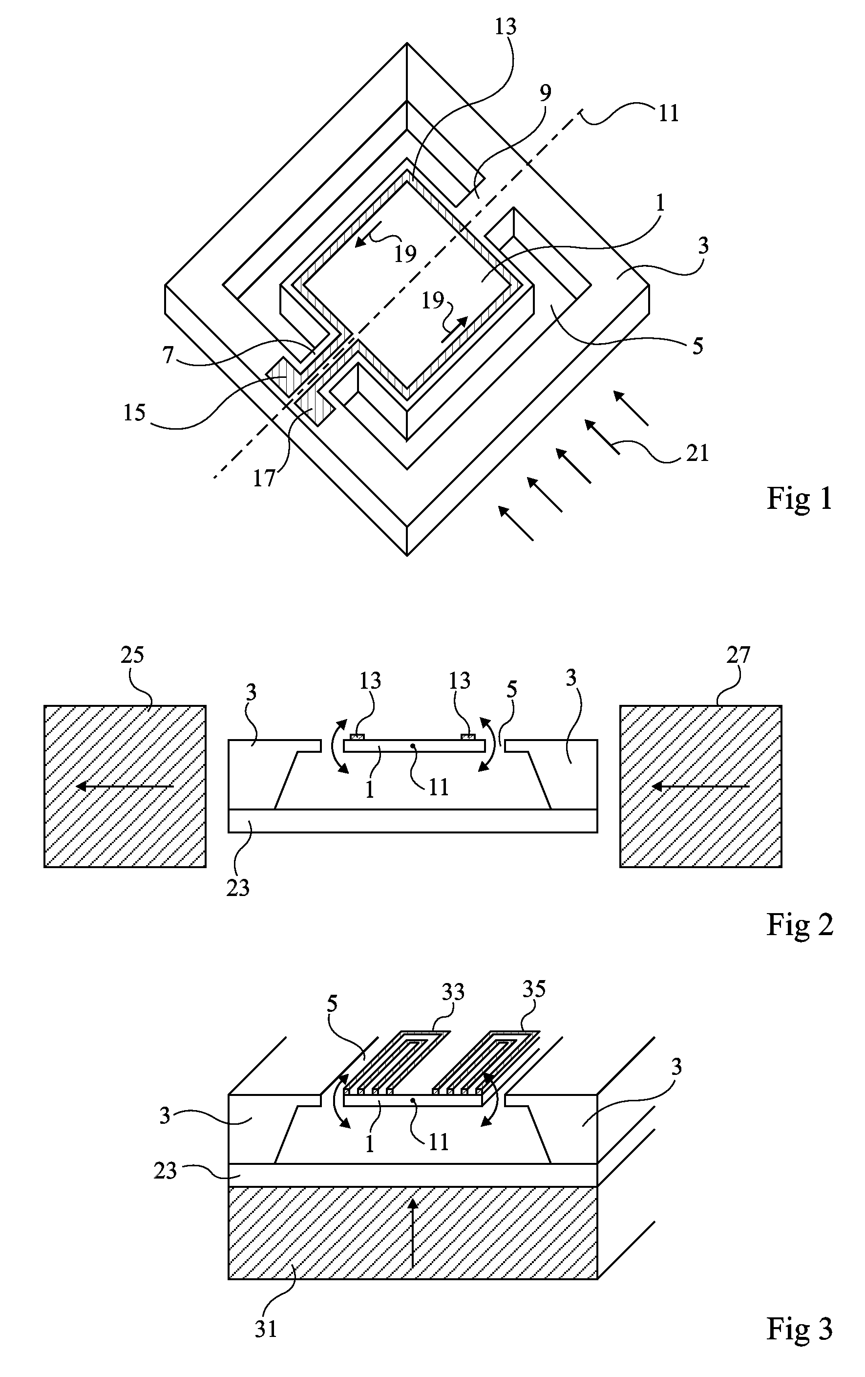
[0038]For clarity's sake, identical elements were designated by the same references in the different drawings and, in addition, as is common in showing micro-components, the various figures are not drawn to scale.

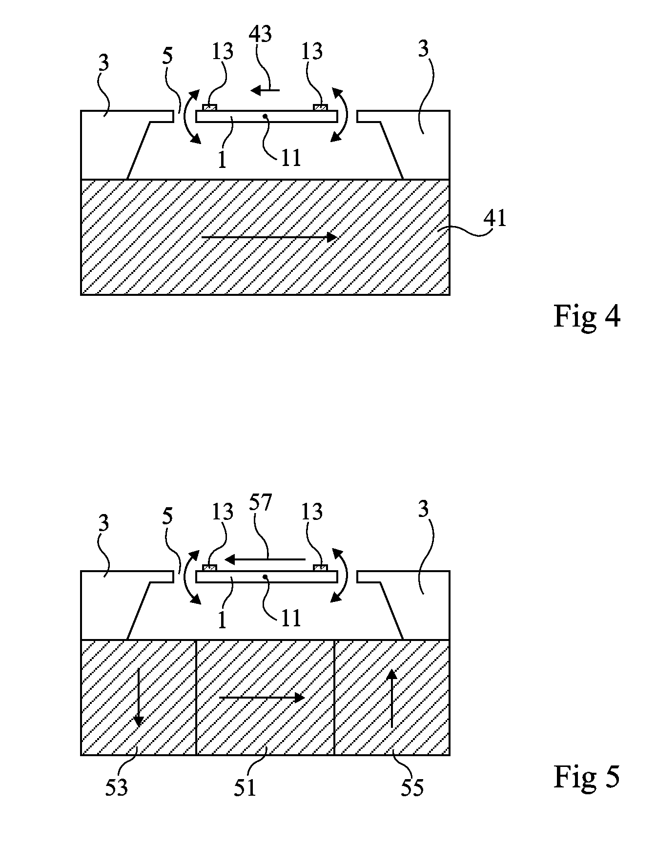
[0039]FIG. 4 is a cross-sectional view schematically showing a sample structure including an electromagnetically actuated micro-mirror, formed in a silicon wafer. Like the structure described in relation to FIG. 2,

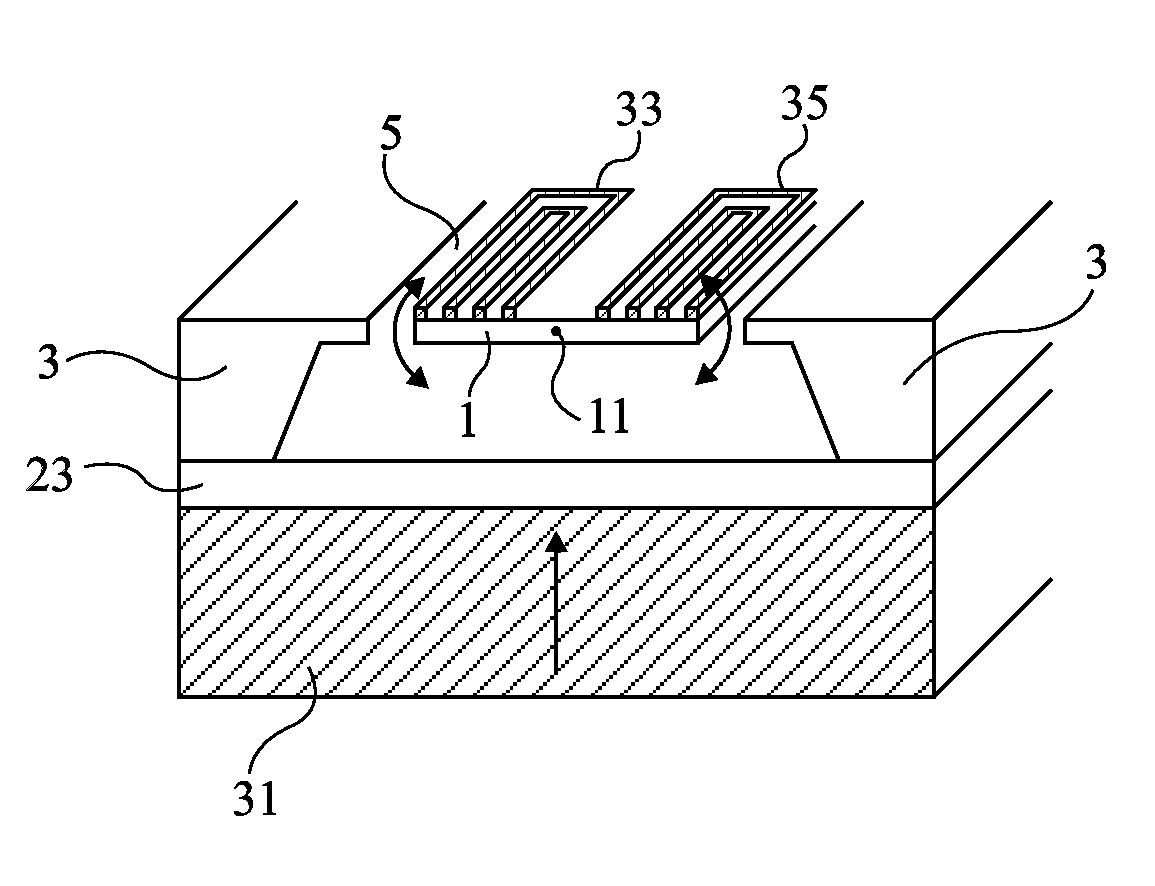
this structure comprises a reflective, moveable plate 1, fixed in a stationary frame 3. A gap 5 separates moveable plate 1 from frame 3. Moveable plate 1 is connected to frame 3 by two, or pairs of arms, not shown, aligned on both sides of the plate along the same axis 11. Thus, plate 1 is rotatable about axis 11.

[0040]A conductive loop 13 follows the periphery of the front face of moveable plate 1. The extremities of path 13 cross, for example, over one of the mounting arms of plate 1 and end in contacts, not shown, formed on frame 3 and suitable for being connec...


PUM


Abstract

The invention relates to an electromagnetically actuated microshutter comprising: a moveable plate that can rotate about an axis, connected to a stationary frame by two arms aligned on both sides of the plate to said axis, and comprising on its periphery a conductive loop; and below the assembly formed by the stationary frame and the moveable plate, a group of magnets having distinct magnetic orientations, arranged in such a manner so as to create, in regard to the moveable plate, a lateral magnetic field, in the plane of the frame, oblique in relation to the axis of rotation.

Description

FIELD OF THE INVENTION[0001]The present invention relates to moveable microshutters formed by production methods for micro-electromechanical systems (MEMS). In particular, it pertains to a new electromagnetically actuated microshutter structure. An example of application of the present invention relates to electromagnetically actuated micro-mirrors.DESCRIPTION OF PRIOR ART[0002]Moveable micro-mirrors based on MEMS technology are used in numerous devices, for example, in miniaturized projection systems, and in visible or infrared light sensors, such as bar code readers. Of interest here are micro-mirrors attached to a frame by an axis and orientatable around this axis by electromagnetic means.[0003]FIG. 1 schematically shows an MEMS structure, formed in a silicon wafer, including an electromagnetically actuated moveable micro-mirror. This structure comprises a reflective, moveable small plate 1, or micro-mirror, attached to a stationary frame 3. A gap 5 extends between moveable plate...

Claims


Application Information

Patent Timeline
IPC IPC(8): G02B26/02
CPCB81B3/0021B81B2201/045B81B2203/0181G02B26/023H02K26/00H02K33/18G02B26/085
Inventor CUGAT, ORPHEEABELE, NICOLAS
Owner GOOGLE LLC
Why Eureka
Try Eureka