Communication system, transmitter and receiver

a communication system and transmitter technology, applied in the field of mobile communication technique, can solve the problem that the mt cannot perform channel estimation, and achieve the effect of reducing the amount of radio resources and improving the accuracy of channel estimation

Active Publication Date: 2013-01-03
SHARP KK
View PDF2 Cites 12 Cited by
  • Summary
  • Abstract
  • Description
  • Claims
  • Application Information

AI Technical Summary

Benefits of technology

[0077]With a spatially-multiplexed nonorthogonal DRS, pilots can be transmitted to all MTs with a single radio resource, and thus enough radio resource for allocating data signals can be ensured. In addition, accuracy of channel estimation can be improved by transmitting the nonorthogonal DRS and the orthogonal DRSs.

Problems solved by technology

On the other hand, if the BS simultaneously transmits the DRSs to multiple MTs by spatial multiplexing using THP as in the case of transmitting a data signal, the MT cannot perform channel estimation.

Method used


Image

  • Communication system, transmitter and receiver
  • Communication system, transmitter and receiver
  • Communication system, transmitter and receiver

Examples


first embodiment

[0110]In a first embodiment of the present invention, a base station (BS) transmits an orthogonal DRS to each mobile terminal MT, and also transmits DRSs for the respective MTs by nonlinear-spatial multiplexing like in the method used for data signals. The DRS is referred to as “nonorthogonal DRS.” The MT performs channel estimation by using both the orthogonal DRS and the nonorthogonal DRS. Hereinafter, a detailed configuration of this embodiment will be described with reference to the drawings.

[0111]1) Configuration of BS

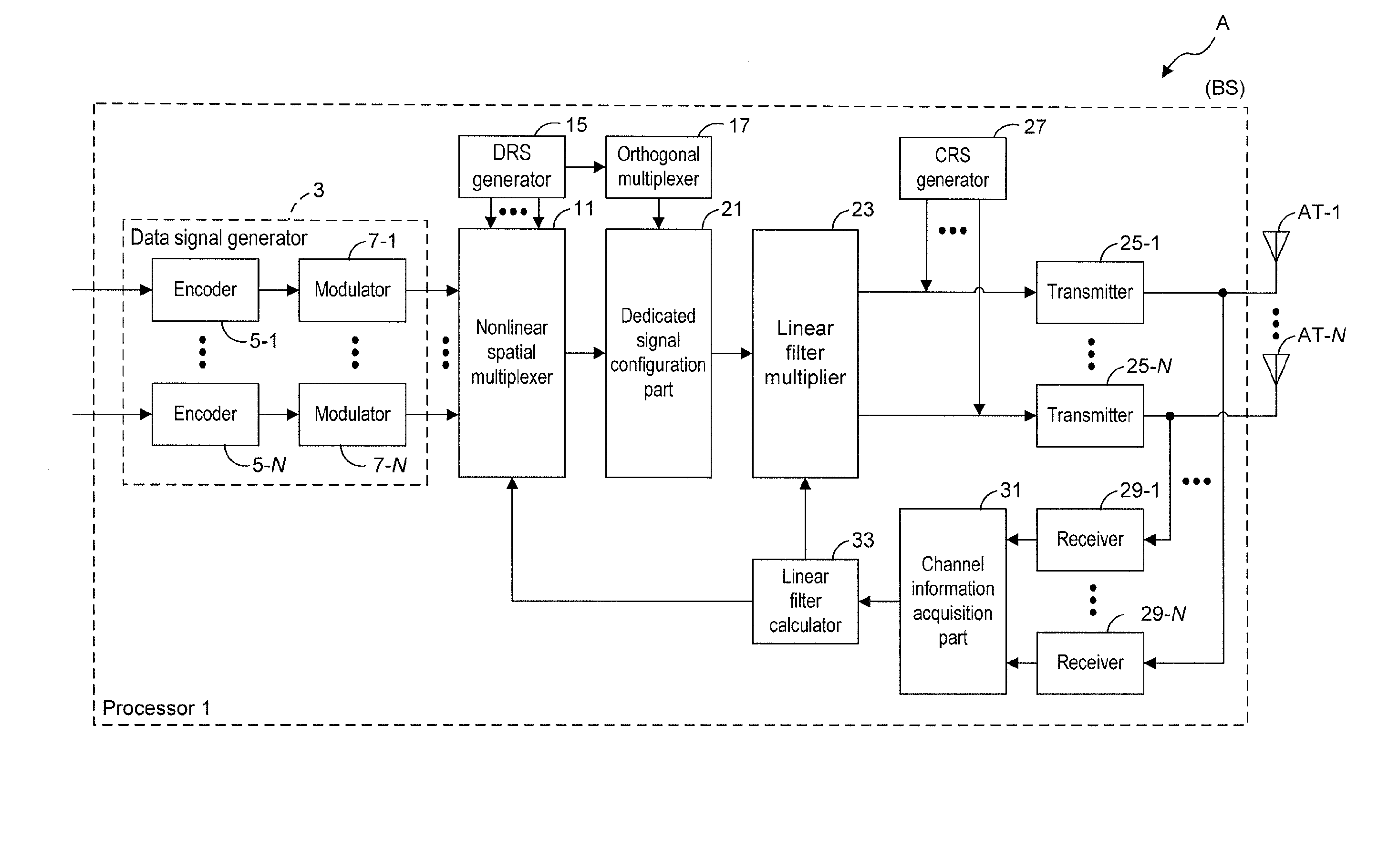
[0112]FIG. 1 is a functional block diagram showing an exemplar configuration of a BS in this embodiment. While the conventional example in FIG. 26 has been described for the case where the number of MTs and the number of antennas of the BS are both two to simplify the description, the exemplar configuration in FIG. 1 will be described for a case including an arbitrary N number of MTs.

[0113]As shown in FIG. 1, a BS (A) generates common reference signals (CRS) for e...

second embodiment

[0162]A description has been given above in the first embodiment of a method of performing channel estimation by using one nonorthogonal DRS. In this embodiment, a description will be given of a method of performing channel estimation by combining multiple nonorthogonal DRSs.

[0163]Unlike the first embodiment, a frame configuration of this embodiment including data signals, orthogonal DRSs and nonorthogonal DRSs is as shown in FIG. 12, for example. In addition, a configuration of a BS of this embodiment can be shown by FIG. 1 as in the case of the first embodiment. A configuration of an MT is shown by FIG. 4A as in the case of the first embodiment. Note, however, that the configuration of the DRS channel estimation part 65 is replaced with a configuration shown in FIG. 13. Unlike FIG. 4B, channel estimation is repeatedly performed (reference numeral L) in FIG. 13 between a combined DRS estimation part 85a and a perturbation vector estimation part 83a. This processing is specifically ...

third embodiment

[0177]In the first and second embodiments, descriptions have been given of cases of single stream communication where the MTs each receive a single data signal at the same time point at the same frequency. The present invention is also applicable to a situation as shown in FIG. 28, where MTs each performing multistream communication are spatially multiplexed.

[0178]Hereinbelow, a description will be given of exemplar configurations of a BS and an MT in this case with reference to the drawings. Like in the first embodiment and the second embodiment, firstly basic single-carrier communication will be described, and then a case of expanding the communication to OFDM will be described as a modified example. In addition, although this embodiment will be described by using a case where each MT communicates using M streams at a time, as an example, the embodiment is not limited to this, and the number of communication streams may vary among the MTs.

[0179]Operations of the BS and the MT of t...


PUM


Abstract

Disclosed is a transmission device including a plurality of antennas for transmitting signals in the same channel at the same time point to a plurality of reception devices, characterized by including: a DRS generator configured to generate DRSs (dedicated reference signals) for the respective reception devices; a nonlinear spatial multiplexer configured to generate a nonorthogonal DRS by use of a first group of DRSs including at least one of the DRSs; and a transmitter configured to transmit a signal containing at least the nonorthogonal DRS.

Description

TECHNICAL FIELD[0001]The present invention relates to a mobile communication technique.BACKGROUND ART[0002]1. Regarding THP[0003]Tomlinson Harashima Precoding (THP) is a technique in which under a situation where interference exists, a transmitter previously knows the interference, previously cancels the interference from a transmission signal and transmits the signal to a receiver. In this process, this method causes both the transmitter and the receiver to carry out a Modulo (remainder) operation to transmit and receive the signal in which an increase in transmission power due to the cancellation of the interference is suppressed (refer to later mentioned non-patent document 1).[0004]A description will be given of the Modulo operation carried out by both the transmitter and the receiver in the communication using THP. The Modulo operation is a process of reducing transmission power by keeping the amplitude of a transmission signal within a certain range or less. To be specific, th...

Claims


Application Information

Patent Timeline
Patent Type & Authority Applications(United States)
IPC IPC(8): H04W4/06H04W4/00
CPCH04B7/0452H04L5/0007H04L5/0051H04J11/0033H04B17/24H04B7/024H04B7/0617H04B7/063H04B7/0658H04L25/0224
Inventor NAKANO, HIROSHIONODERA, TAKASHITO, SHIMPEIHIRATA, KOZUETOMEBA, HIROMICHI
Owner SHARP KK
Why Eureka
Try Eureka