Multi-Rotor Apparatus and Method for Motion Sculpting

a multi-rotor apparatus and motion sculpting technology, applied in the field of muscle trainers and methods of exercising muscles, can solve the problems of undesirable dominant muscle condition and its attendant disadvantages, and achieve the effect of convenient manipulation and managemen

Active Publication Date: 2013-01-03
PRIESTER WILLIAM B
View PDF5 Cites 32 Cited by
  • Summary
  • Abstract
  • Description
  • Claims
  • Application Information

AI Technical Summary

Benefits of technology

[0017]To better represent the movement of the entire golf club in space, the position of the club face will hereinafter be referred to as the club face plane. Regardless of the loft of the club face, the club face plane represents the position of the club face as if the club face had zero degrees of loft. Unlike the club shaft plane that typically has some degree of curvature, the club face plane is a true plane since it is an extension of the zero degree club face. The concepts of the club face plane and the club shaft plane help one to visualize the relationship between the movement of the club face and the club shaft during the golf swing. An approximation of the proper relationship between these two planes is described in a “two-plane-merger” golf swing theory.
[0035]Speed is a swing variable that is influenced by the combined actions of all the opposing muscle groups in the swing. The speed of the backswing is typically slower than the speed of the downswing. Variation in the speed of the swing and the timing of the transition between the backswing and downswing create the tempo of the swing. Speed and tempo are much easier to manipulate and manage once the golfer has acquired the proper muscle memory for their ideal club shaft plane, ideal two-plane merger, ideal hinging, ideal arc and ideal performance of other opposing muscle groups.

Problems solved by technology

This undesirable dominant muscle condition and its attendant disadvantages are particularly apparent in sporting games such as, for example, the game of golf, where the implement is a golf club and the individual is a golfer.
However, the ideal club shaft path does not typically coincide with a true plane like a sheet of glass.

Method used


Image

  • Multi-Rotor Apparatus and Method for Motion Sculpting
  • Multi-Rotor Apparatus and Method for Motion Sculpting
  • Multi-Rotor Apparatus and Method for Motion Sculpting

Examples


Embodiment Construction

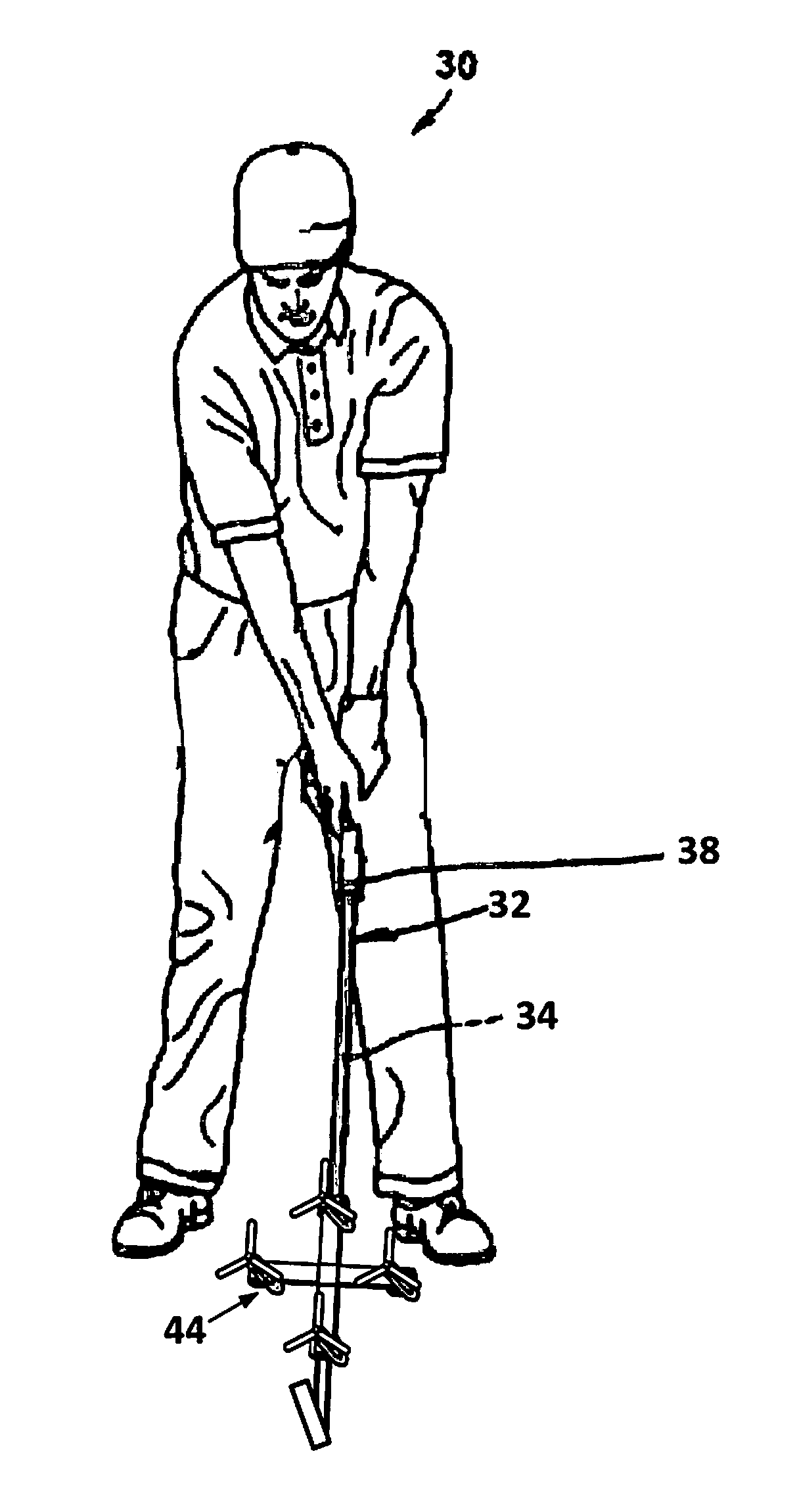
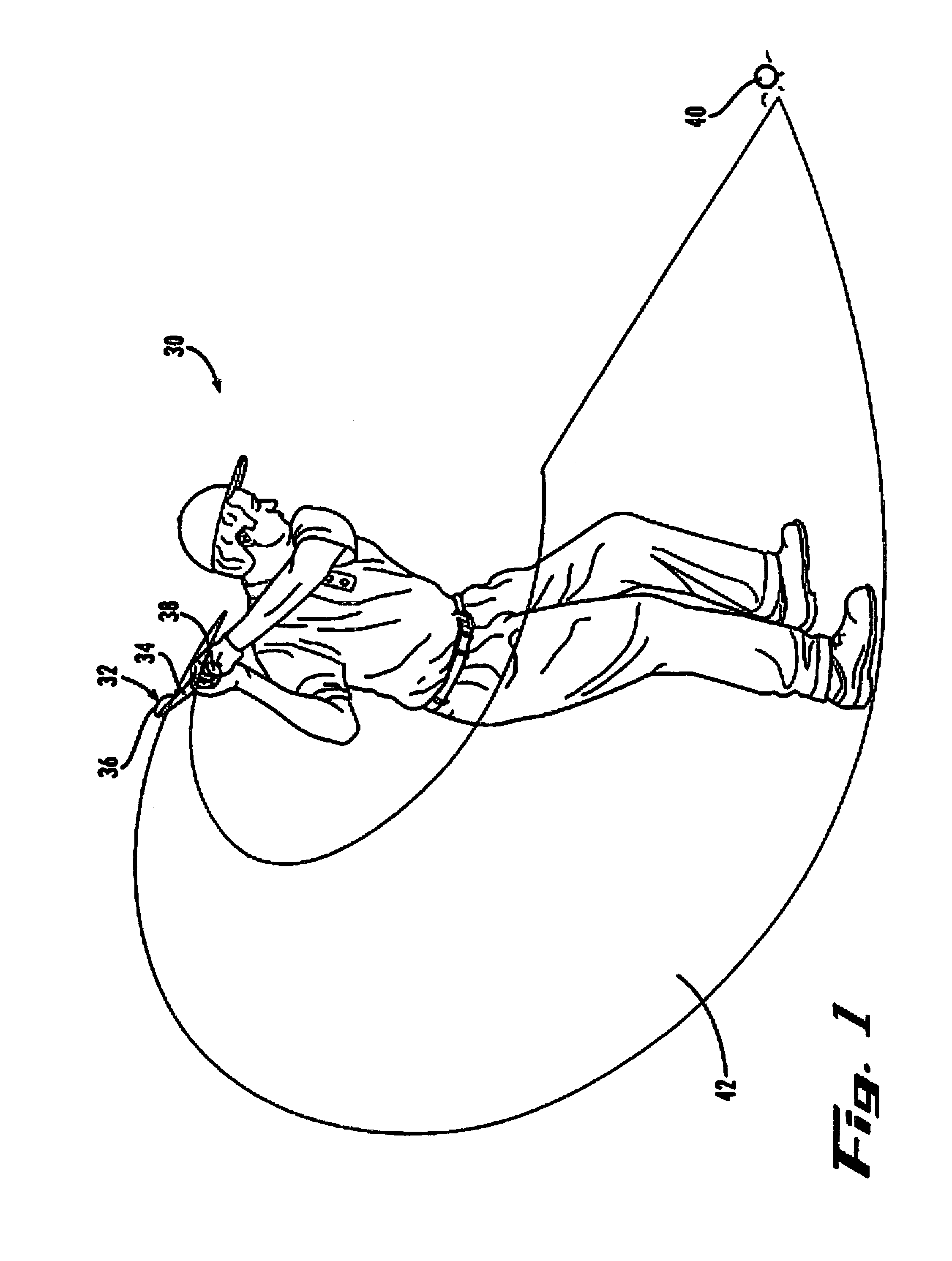
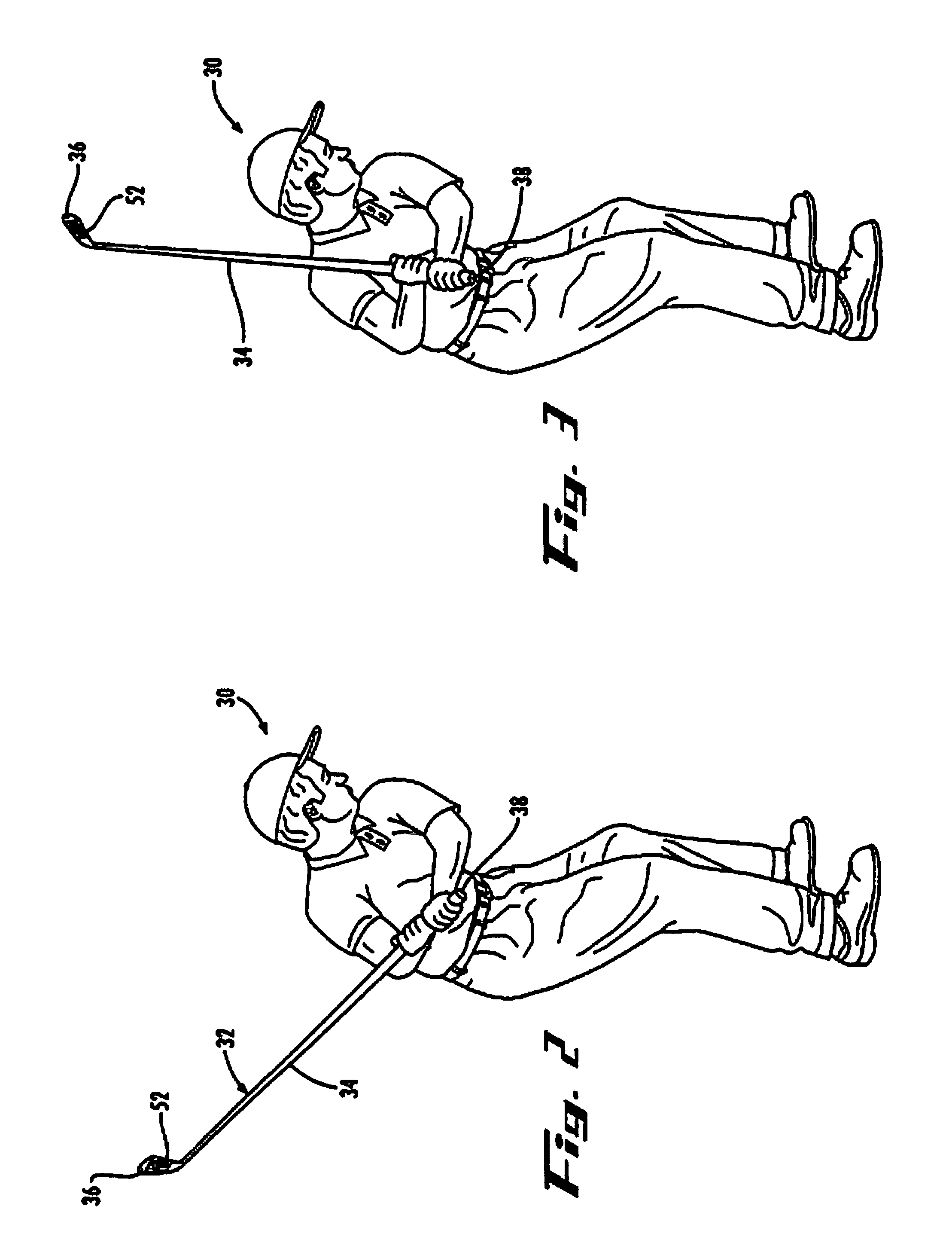
[0123]Referring to FIG. 1, a golfer 30 has completed a backswing of a golf club 32, with the club being at the peak of the backswing, or backswing-completion position, and poised for the beginning of a downswing of the club, in anticipation of the completion of a full stroke. The club 32 includes a club shaft 34 extending between a distal end and a proximal end thereof. A club head 36 is mounted on the distal end of the shaft 34, and a grip 38 is formed about a portion of the shaft at or near the proximal end of the shaft.

[0124]The grip 38 typically extends from its outboard end disposed at the proximal end of the shaft 34 towards the distal end of the shaft, and terminates at an inboard end of the grip along an intermediate portion of the shaft. In preparation for swinging the club 32, the golfer 30 positions the golfer's hands on the grip 38 in a conventional club-gripping manner, whereby the thumb of one hand, for example, the right hand, is closer to the inboard end of the grip ...


PUM


Abstract

A reversibly attachable muscle trainer includes a multi-arm structure with motion sensors and force generators for exercising opposing muscles of a person moving an implement so as to maintain an ideal movement. When attached to the implement, the muscle trainer trains the opposing muscles to consistently move the implement in an ideal way. While the person moves the implement with the muscle trainer attached, a processor receives signals from the motion sensors and determines differences between the actual implement motion and an ideal implement motion. The difference indicates a dominating force direction in which the dominating muscles urge the implement. The processor activates the force generators to apply external forces to the implement to urge the implement in various types of training force directions.

Description

RELATED APPLICATIONS[0001]This application claims priority as a continuation-in-part to co-pending U.S. patent application Ser. No. 12 / 237,502 filed Sep. 25, 2008, titled “Muscle Training Apparatus and Method,” which is a continuation-in-part of U.S. patent application Ser. No. 11 / 857,049 filed Sep. 18, 2007, which issued as U.S. Pat. No. 7,766,760 which is a continuation-in-part of U.S. patent application Ser. No. 10 / 681,971 filed Oct. 9, 2003, which issued as U.S. Pat. No. 7,351,157. This application also claims priority as a continuation-in-part of co-pending U.S. patent application Ser. No. 11 / 376,974 filed Mar. 16, 2006, titled “Motion Training Apparatus and Method” and U.S. provisional patent application Ser. No. 61 / 624,732 filed Apr. 16, 2012, titled “Multi-rotor Apparatus and Method for Motion Sculpting.” The entire contents of these prior applications are incorporated herein by reference.FIELD[0002]This invention relates to a muscle trainer and to methods of exercising a mu...

Claims


Application Information

Patent Timeline
Patent Type & Authority Applications(United States)
IPC IPC(8): A63B69/36
CPCA63B24/0003A63B69/3614A63B69/3623A63B69/3632A63B2207/02A63B2220/40A63B2225/09A63B71/06G09B19/0038A63B2071/0602A63B2071/0627A63B2225/01A63B2220/806A63B21/06A63B2225/50A63B71/0622A63B2071/0655A63B2220/20A63B2220/30A63B2220/34A63B2225/74A63F13/285
Inventor PRIESTER, WILLIAM B.MAY, RICHARD E.DAWSON, C. BRYANWARD, DAVID A.PINGEN, GEORG
Owner PRIESTER WILLIAM B
Why Eureka
Try Eureka