
Assembly for use with a syringe

a technology of syringe and assembly, which is applied in the direction of infusion syringe, infusion needle, intravenous device, etc., can solve the problems of failed injection, difficult administration of id injection, and loss of delivered compound on the skin surfa

Active Publication Date: 2013-01-03
SID TECH LLC
View PDF39 Cites 9 Cited by
  • Summary
  • Abstract
  • Description
  • Claims
  • Application Information

AI Technical Summary

Benefits of technology

The present invention provides an assembly for use with a syringe that includes a sealing element and an adapter with two skin contacting surfaces. The assembly also includes a needle shield that surrounds at least one of the adapter and the syringe barrel. The technical effect is that this assembly improves the stability and functionality of the syringe and reduces the risk of needle damage during use.

Problems solved by technology

Administering an ID injection can be difficult and generally requires an experienced nurse or medical professional.
Incorrect placement of the tip of a cannula or needle may lead to a failed injection.
Incorrect placement of the cannula may also puncture the skin again after being inserted into the dermis, with the delivered compound being lost on the surface of the skin.
The insertion of the cannula at an incorrect angle and / or depth results in a failed ID injection, which is typically repeated, causing additional pain and discomfort to the patient, as well as ineffective treatment to the patient.
ID injection has been considered for immunization in the past, but has generally been rejected in favor of more reliable intramuscular or subcutaneous routes of administration because of the difficulty in making a successful ID injection, particularly when the injections are administered by relatively unskilled healthcare professionals.
The technique is known to be quite difficult to perform and generally requires specialized training.
A degree of imprecision in the placement of the injection results in a significant number of false negative test results.
ID injections are generally limited in volume to about 0.1 milliliter (ml), which is not enough for many common drugs.

Method used


Image

  • Assembly for use with a syringe
  • Assembly for use with a syringe
  • Assembly for use with a syringe

Examples


Embodiment Construction

[0044]Certain terminology is used in the following description for convenience only and is not limiting. The words “right” and “lower” designate directions in the drawings to which reference is made. The words “inwardly,”“outwardly,”“proximally” and “distally” refer to directions toward and away from, respectively, the geometric center or orientation of the assembly, the syringe or other related parts thereof. The words “connect,”“connectable” and “connected” mean joined or linked together, either by direct engagement or through intermediate components. Unless specifically set forth herein, the terms “a,”“an” and “the” are not limited to one element, but instead should be read as meaning “at least one.” The terminology includes the above-listed words, derivatives thereof and words of similar import.

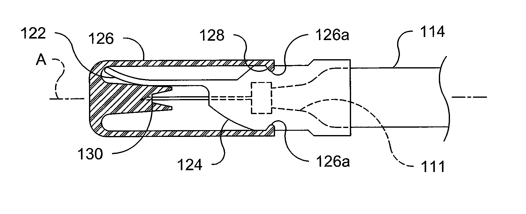
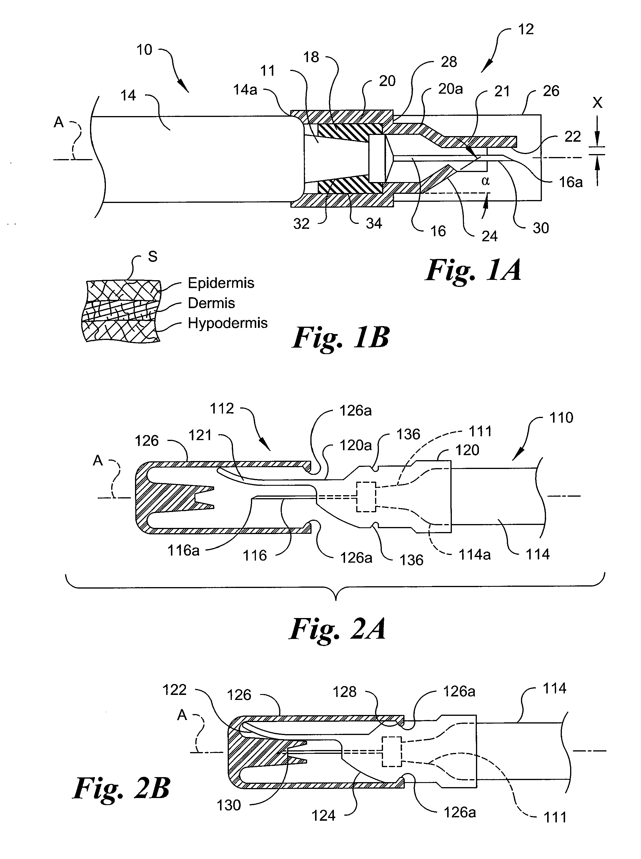
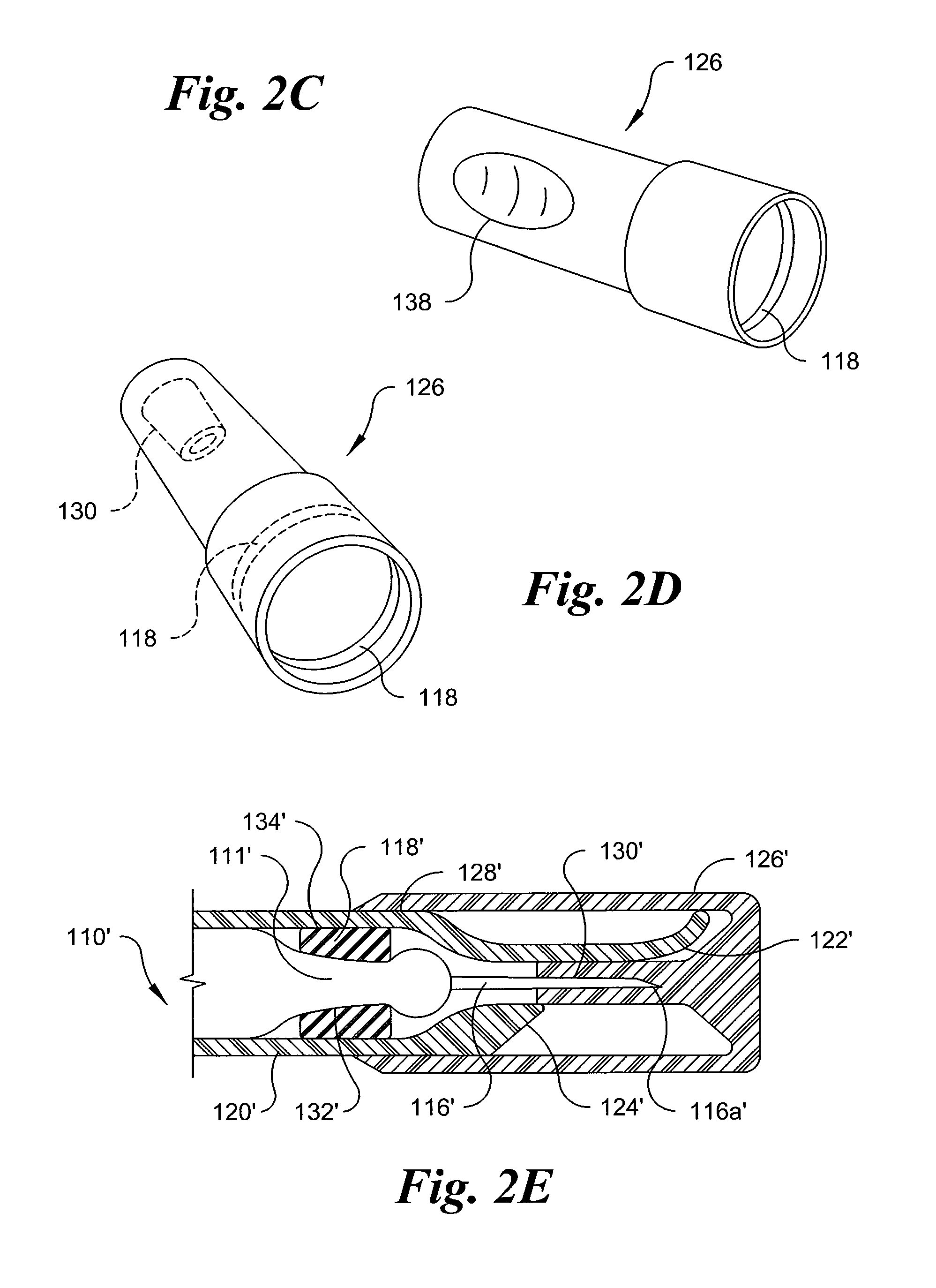
[0045]Referring to the drawings in detail, wherein like numerals indicate like elements throughout the views, FIG. 1A shows a first preferred embodiment of a combination of a syringe 10 a...


PUM


Abstract

An assembly for use with a syringe having a barrel and a needle includes a sealing element surrounding and positioned over at least a portion of the distal end of the syringe. An adapter at least partially surrounds the sealing element and is positioned over the distal end of the syringe. The adapter has a first skin contacting surface positioned at a distal end thereof. At least a portion of the first skin contacting surface extends generally parallel to at least a terminal end of the needle. The adapter also has a second skin contacting surface positioned proximally relative to the terminal end of the needle and at an angle to the first skin contacting surface. A needle shield at least partially surrounds and is removably positioned over at least one of the adapter, the sealing element and the syringe barrel.

Description

CROSS-REFERENCE TO RELATED APPLICATIONS[0001]The present application claims the benefit of U.S. Provisional Patent Application No. 61 / 339,933, filed Mar. 12, 2010 and entitled “NEEDLE ASSEMBLIES AND PREFILLED SYRINGES FOR INTRADERMAL INJECTION,” the entire subject matter of which is hereby incorporated by reference.BACKGROUND OF THE INVENTION[0002]The present invention is generally directed to an assembly for use with a syringe and, more particularly, to a combination of a syringe and an assembly having a sealing element, an adapter and a needle shield.[0003]Intradermal (“ID”) injections are used for delivering a variety of diagnostic and treatment compositions into a patient. ID injections are typically injections of a relatively small amount of medicament into the dermis, the dermal layer or even into a lower portion of the epidermis of a patient's skin (FIG. 1B). Substances may be injected intradermally for diagnostic testing, such as to determine a patient's immunity status agai...

Claims


Application Information

Patent Timeline
IPC IPC(8): A61M5/32
CPCA61M5/158A61M2005/1585A61M5/46A61M5/3287A61M5/24A61M5/425
Inventor TSALS, IZRAILEVANS, CHRISTOPHERCOSTELLO, BRIAN
Owner SID TECH LLC
Learn More