
Collaborative Software Debugging In A Distributed System With Private Debug Sessions

a distributed system and software debugging technology, applied in the field of data processing, can solve the problems of complex source code development, unavailability of remote distributed developers' debugging engines, and the development of software source cod

Inactive Publication Date: 2013-01-03
IBM CORP
View PDF20 Cites 28 Cited by
  • Summary
  • Abstract
  • Description
  • Claims
  • Application Information

AI Technical Summary

Benefits of technology

The present invention is about methods, apparatus, and products for collaborative software debugging in a distributed system. The system includes a debug server, multiple bug clients, and a network. The debug server receives application-level messages from the bugs clients, routes them to the back-end debugger, and returns client-specific results to the customers. The technical effect of this invention is that it allows multiple bug clients to collaborate with the bug server to effectively troubleshoot software bugs in a distributed system.

Problems solved by technology

Software source code is increasingly complex and is often developed by various developers, sometimes physically dispersed from one another.
One part of software development, source code debugging, is especially complex in today's distributed software development environments.
Further, during such debugging, developers may have differing interests in different portions of the source code.
At present, there are no debug engines available that enable remotely distributed developers to debug the same source code collaboratively in real-time, while separately viewing different results of the same debugging.

Method used


Image

  • Collaborative Software Debugging In A Distributed System With Private Debug Sessions
  • Collaborative Software Debugging In A Distributed System With Private Debug Sessions
  • Collaborative Software Debugging In A Distributed System With Private Debug Sessions

Examples


Embodiment Construction

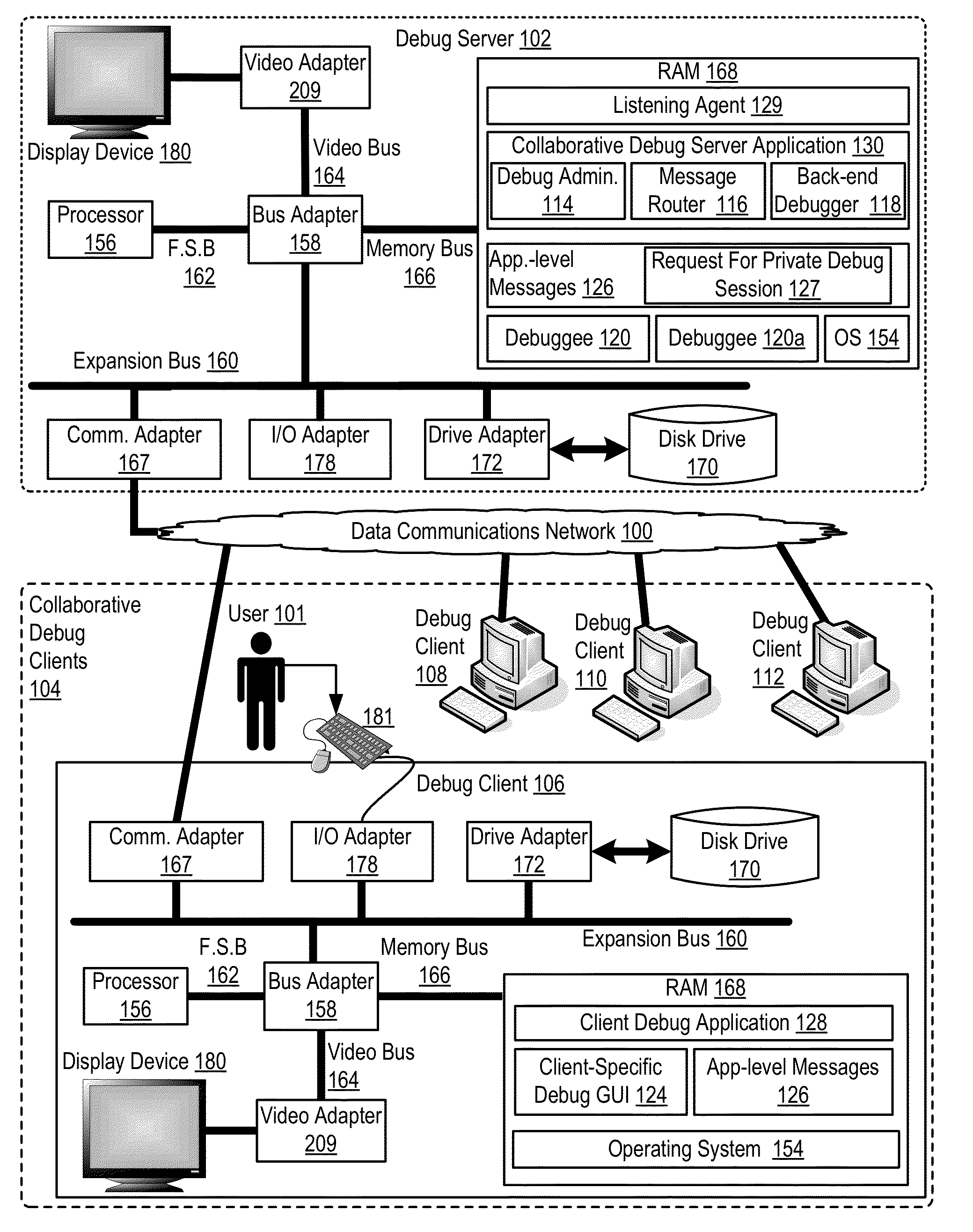
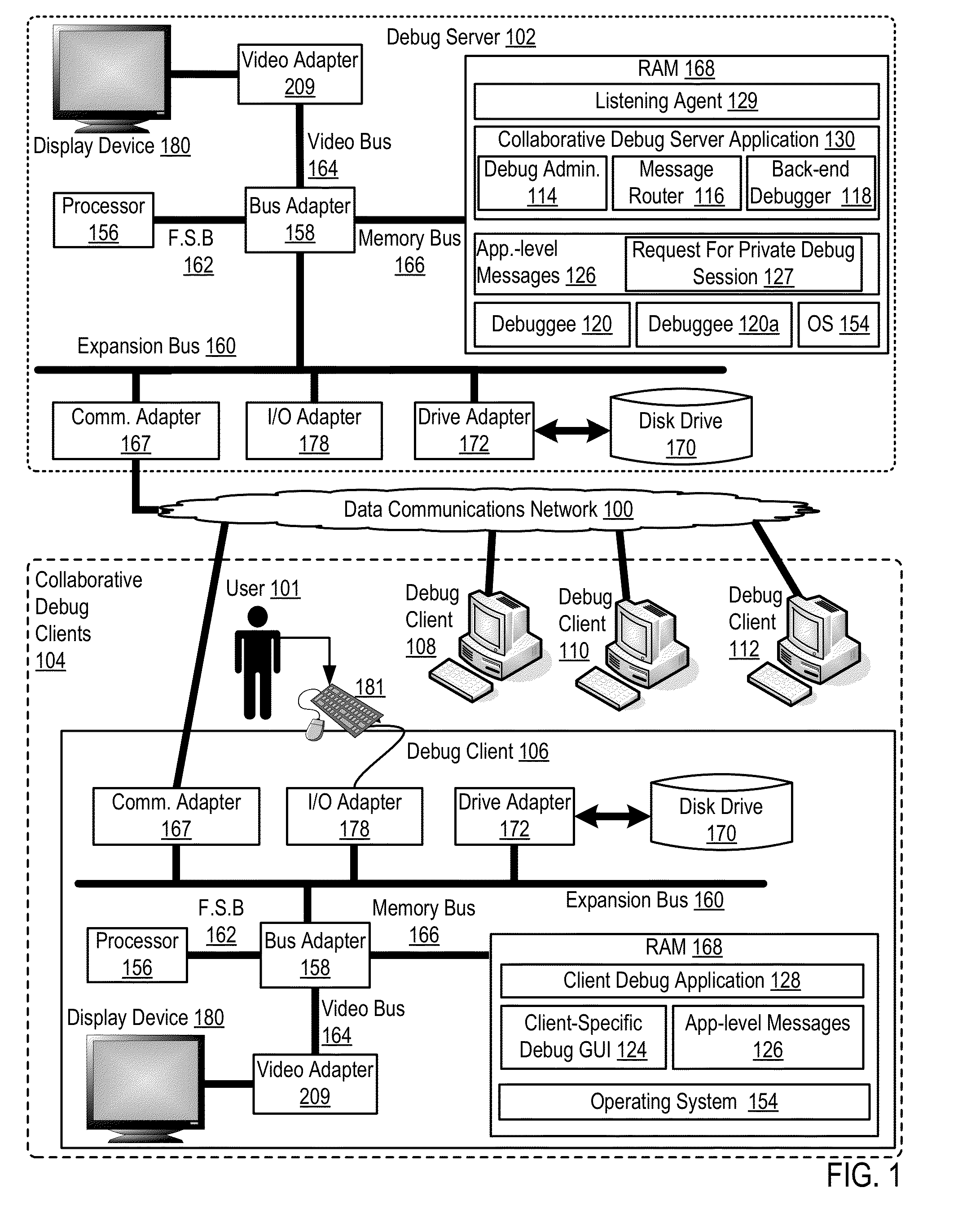
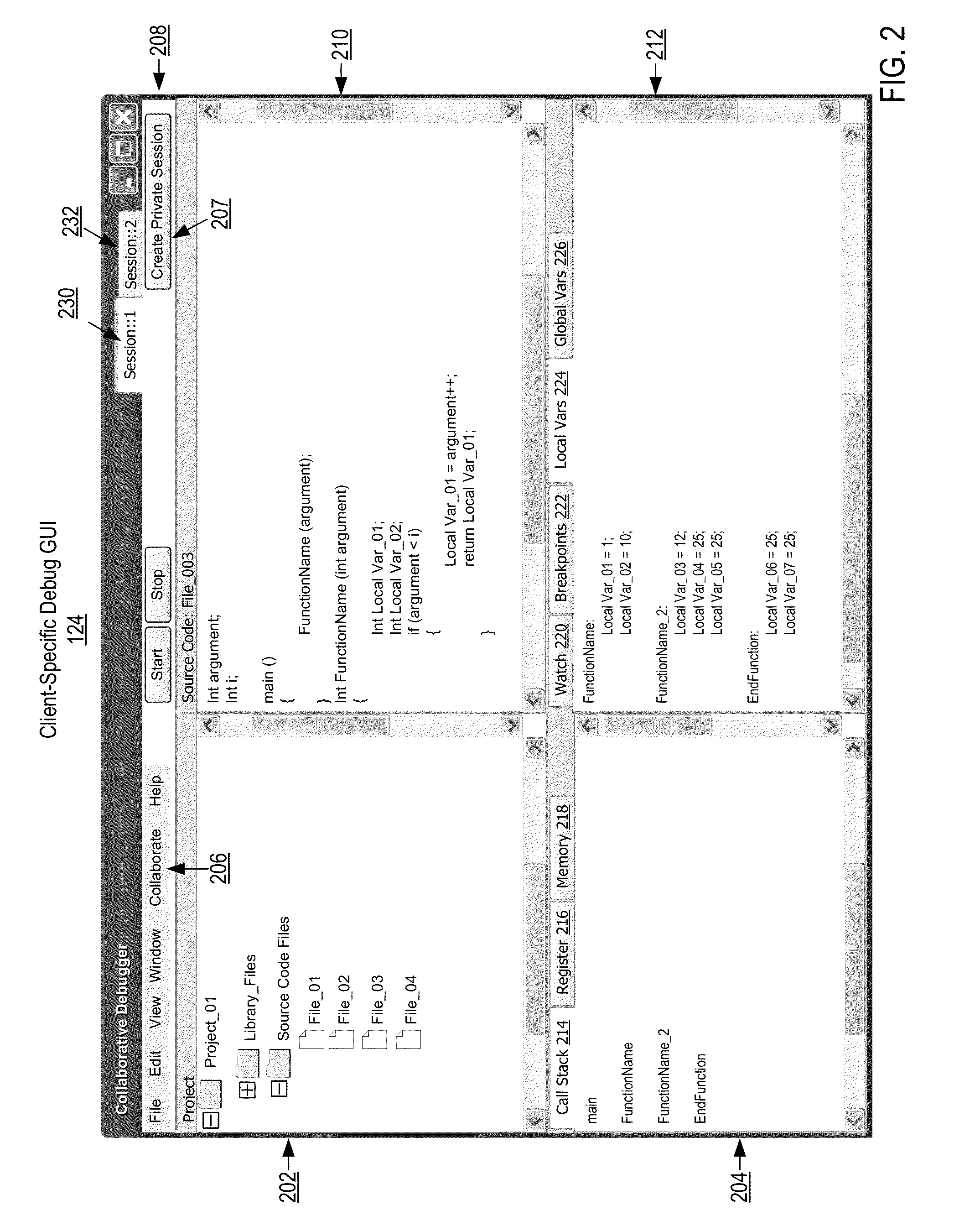
[0020]Exemplary methods, apparatus, and products for collaborative software debugging in a distributed system in accordance with the present invention are described with reference to the accompanying drawings, beginning with FIG. 1. FIG. 1 sets forth a network diagram of a distributed system in which collaborative software debugging is carried out according to embodiments of the present invention. The term ‘debug,’ and its variations—debugged, debugging, and so on—as used in this specification generally refers to a methodical process of finding and reducing the number of bugs, or defects, in a computer program, that is, in source code of the computer program. Debugging may also be carried out to produce other results—decrease source code size, increase efficiency of the source code, decrease memory use by the executed source code, and so on as will occur to readers of skill in the art. The source code of a software program or application being debugged is referred to in this specifi...


PUM


Abstract

In a distributed system that includes a debug server and debug clients coupled for data communications through a data communications network, where the debug server includes a debug administrator, a message router, a back-end debugger, and a debuggee, collaborative software debugging includes receiving, by the debug server from the debug clients, application-level messages including receiving, from a requesting debug client, a request to establish a private debug session of the debuggee; routing, by the message router, the application-level messages among the debug clients, the debug administrator, and the back-end debugger, including forwarding, to the back-end debugger, the request to establish a private debug session of the debuggee; and; and returning, by the debug server to the debug clients in response to the application-level messages routed to the back-end debugger, client-specific debug results, including establishing the private debug session of the debuggee for the requesting debug client.

Description

BACKGROUND OF THE INVENTION[0001]1. Field of the Invention[0002]The field of the invention is data processing, or, more specifically, methods, apparatus, and products for collaborative software debugging in a distributed system.[0003]2. Description of Related Art[0004]Software source code is increasingly complex and is often developed by various developers, sometimes physically dispersed from one another. One part of software development, source code debugging, is especially complex in today's distributed software development environments. In debugging, it is often useful for two or more developers to work together in real-time to debug the source code. Further, during such debugging, developers may have differing interests in different portions of the source code. At present, there are no debug engines available that enable remotely distributed developers to debug the same source code collaboratively in real-time, while separately viewing different results of the same debugging.SUM...

Claims


Application Information

Patent Timeline
IPC IPC(8): G06F9/44
CPCG06F11/362
Inventor BATES, CARY L.
Owner IBM CORP
Learn More