Reactor fuel elements and related methods

a fuel element and reactor technology, applied in nuclear elements, greenhouse gas reduction, nuclear engineering, etc., can solve the problems of increasing power output per area, fuel cladding tubes are still susceptible to stress corrosion cracking, propagation of cracks and depressurization of fuel cladding tubes

Inactive Publication Date: 2013-01-10
BATTELLE ENERGY ALLIANCE LLC
View PDF3 Cites 45 Cited by
  • Summary
  • Abstract
  • Description
  • Claims
  • Application Information

AI Technical Summary

Problems solved by technology

Increased demands on such components are in the form of longer required residence times, thinner structural members, and increased power output per area, which cause corrosion.
Nonetheless, fuel cladding tubes are still susceptible to stress corrosion cracking during operation due to fission products and the radiation-induced swelling of fuels disposed within the cladding tubes.
The interaction between the fission gases produced by the fuel and the fuel itself and the cladding results in nucleation and propagation of cracks and depressurization of the fuel cladding tube.
For example, a significant in-reactor life-limiting use with currently available fuel cladding tubes is corrosion, especially in the presence of water and increased operating temperatures of newer generations of nuclear reactors, such as light water reactors (LWRs) and supercritical water-cooled reactors (SCWRs).
Corrosion of the cladding may be caused by the fission gases present in the gap between the fuel in the cladding tube and the cladding and the interaction between the fuel and the cladding tube as the fuel expands due to thermal expansion of the fuel.
Lower gap thermal conductivity between the fuel and the cladding may reduce the life of the fuel rod by increasing the centerline temperature of the fuel, for example, by increasing the thermal expansion of the fuel thereby leading to greater deformation and corrosion of the cladding.
These chemical reactions, when they occur, result in corrosion of the metal cladding and a consequent weakening of the cladding, which is the primary barrier that prevents the radioactive gases release.
For example, buildup of oxide material on the fuel cladding tubes formed with zirconium caused by oxidation of zirconium during reactor operation may lead to adverse effects on thermal conduction.
The presence of the precipitates may reduce mechanical strength of the fuel cladding tube causing cracks in walls and end caps.
Such cracks propagate from an internal surface of the fuel cladding tube to an external surface and, thus, may rupture the cladding wall.
Depressurization of the fuel cladding tube due to stress corrosion cracking significantly reduces the life of the fuel cladding tube and, in addition, reduces the output and safety of the nuclear reactor.
Deformation of the fuel cladding tube resulting from such tension increases susceptibility of the fuel cladding tube to stress corrosion failure.

Method used


Image

  • Reactor fuel elements and related methods
  • Reactor fuel elements and related methods
  • Reactor fuel elements and related methods

Examples


Embodiment Construction

[0015]In the following detailed description, reference is made to the accompanying drawings that depict, by way of illustration, specific embodiments in which the disclosure may be practiced. However, other embodiments may be utilized, and structural, logical, and configurational changes may be made without departing from the scope of the disclosure. The illustrations presented herein are not meant to be actual views of any particular fuel element or component thereof, but are merely idealized representations that are employed to describe embodiments of the present disclosure. The drawings presented herein are not necessarily drawn to scale. Additionally, elements common between drawings may retain the same numerical designation.

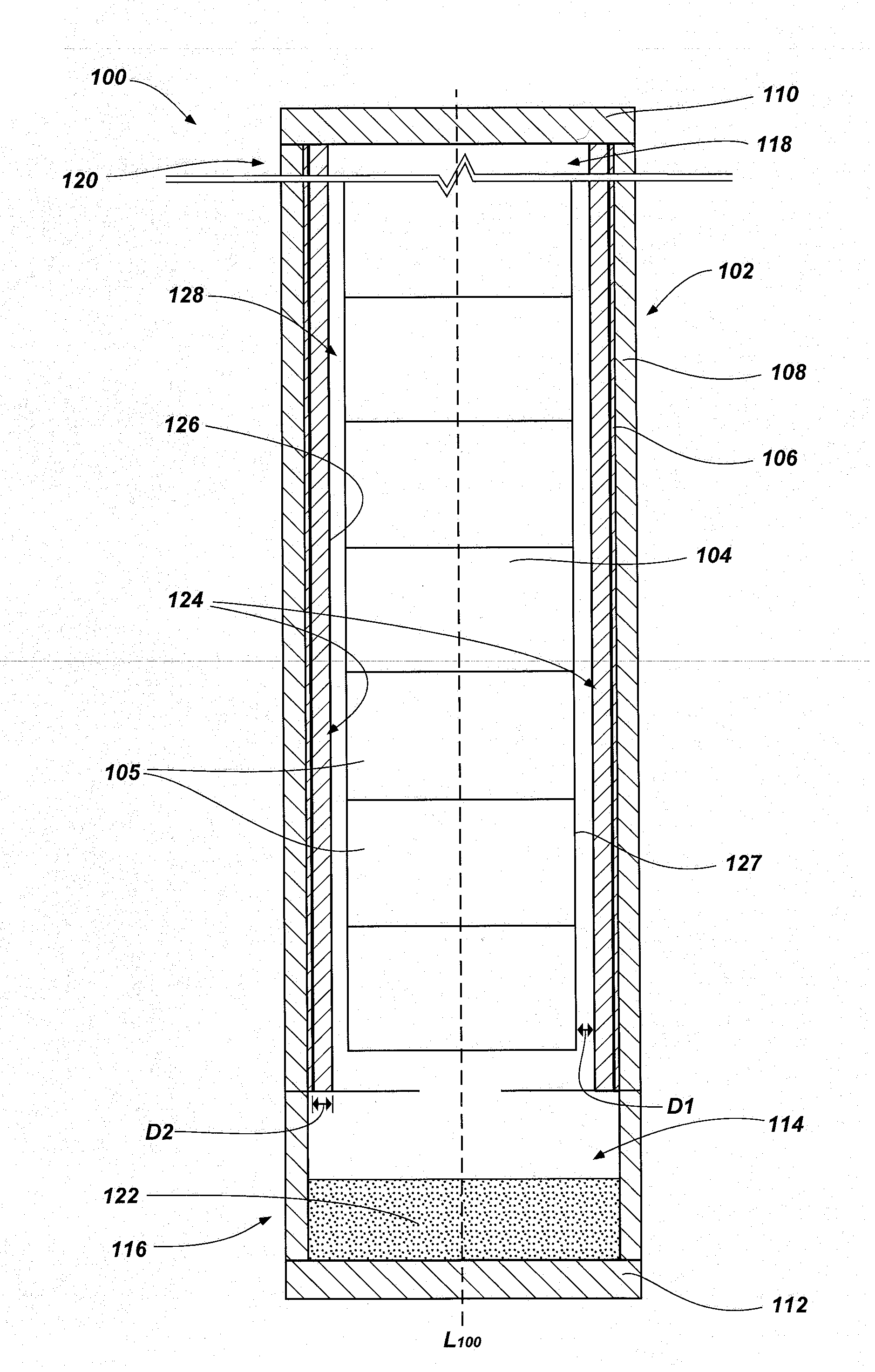
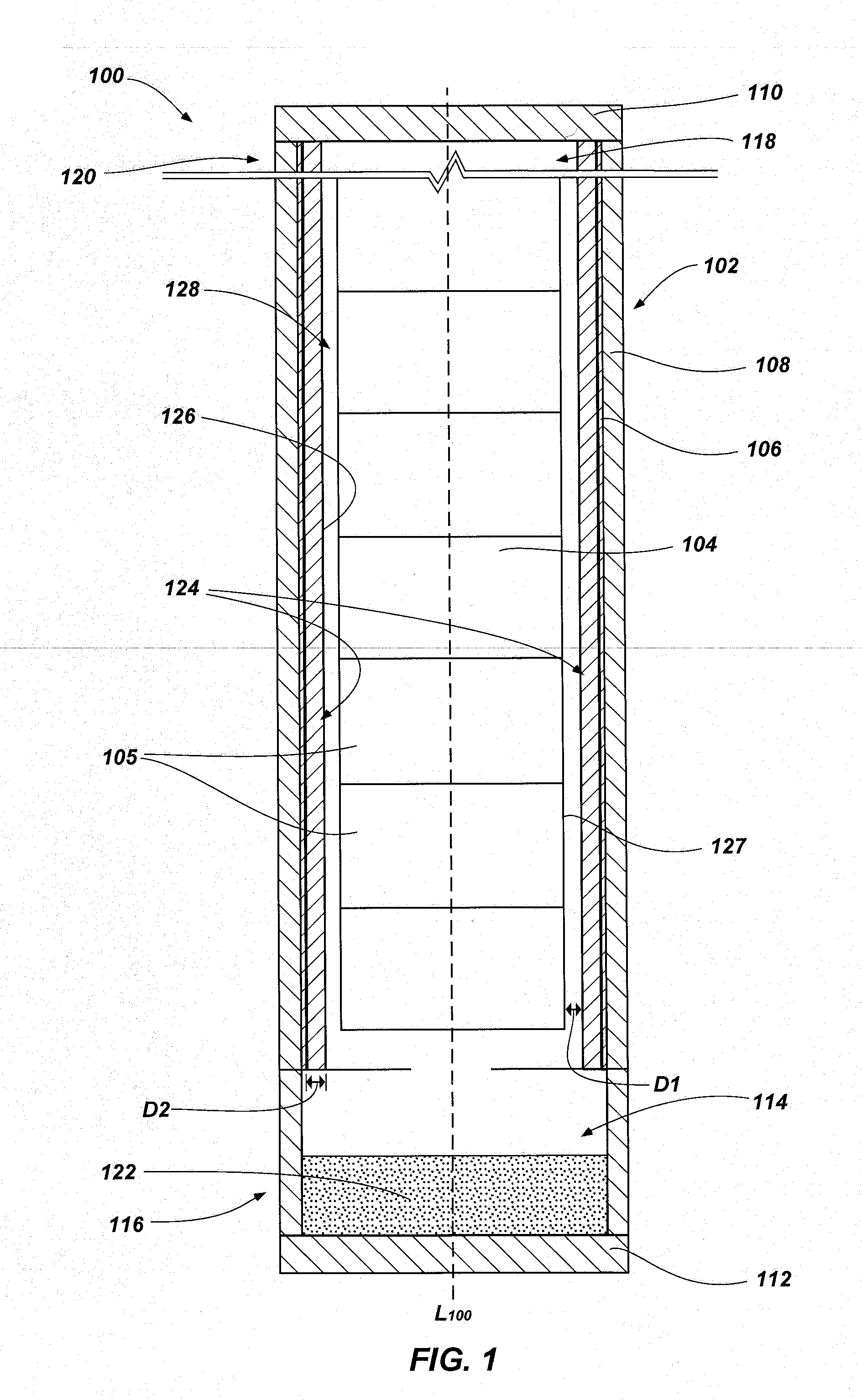
[0016]FIG. 1 is a cross-sectional side view illustrating an embodiment of a fuel element according to the present disclosure. As shown in FIG. 1, a fuel element 100 (e.g., a fuel rod) may include cladding (e.g., a cladding tube 102) and fuel 104 (e.g., nucle...


PUM


Abstract

Fuel elements for use in reactors include a cladding tube having a longitudinal axis and fuel disposed therein. At least one channel is formed in at least one of the fuel and the cladding tube and extends in a direction along the longitudinal axis of the cladding tube. The fuel element further includes a plenum having at least one getter material disposed therein. Methods of segregating gases in fuel elements may include forming a temperature differential in the fuel element, enabling at least one gas to travel into at least one channel formed in the fuel element, and retaining a portion of the at least one gas with at least one getter material. Methods of segregating gases in fuel elements also may include enabling at least one gas to travel through at least one channel of a plurality of channels formed in the fuel element.

Description

STATEMENT REGARDING FEDERALLY SPONSORED RESEARCH OR DEVELOPMENT[0001]This invention was made with government support under Contract Number DE-AC07-051D14517 awarded by the United States Department of Energy. The government has certain rights in the invention.TECHNICAL FIELD[0002]Embodiments of the present disclosure relate generally to fuel elements for use in nuclear reactors. More particularly, embodiments of the present disclosure relate to fuel elements including at least one channel formed therein and one or more getter materials to facilitate the separation and containment of gases within the fuel element, and methods related thereto.BACKGROUND[0003]Nuclear reactor fuel designs, such as pressurized water reactor and boiling water reactor fuel designs, impose significantly increased demands nuclear fuel cladding tubes. Such components are conventionally fabricated from the zirconium-based metal alloys, such as zircaloy-2 and zircaloy-4. Increased demands on such components are ...

Claims


Application Information

Patent Timeline
Patent Type & Authority Applications(United States)
IPC IPC(8): G21C3/00
CPCG21C3/17Y02E30/40G21C2003/047G21C3/047Y02E30/30
Inventor GARNIER, JOHN E.GRIFFITH, GEORGE W.GLAZOFF, MICHAEL V.RASHKEEV, SERGEY
Owner BATTELLE ENERGY ALLIANCE LLC
Why Eureka
Try Eureka