Modeling and desired control of an energy-storing prosthetic knee

a technology of prosthetic knees and knees, applied in the field of applicability and method of use of a prosthetic knee, can solve the problems of overuse injuries and osteoarthritis, limbs that are not quite compliant, and the energy cost of walking is 30-50% higher in unilateral transfemoral amputees than in able-bodied peopl

Inactive Publication Date: 2013-01-10
THE CLEVELAND CLINIC FOUND
View PDF2 Cites 31 Cited by
  • Summary
  • Abstract
  • Description
  • Claims
  • Application Information

AI Technical Summary

Benefits of technology

[0008]In an embodiment of the present invention, an energy-storing prosthetic knee is described. An upper leg structure is configured to attach to a socket for a transfemorally amputated residual limb. A lower leg structure is hingedly connected to the upper leg structure and is configured to attach to a lower limb prosthesis. The lower and upper leg structures move pivotally relative to one another during a gait cycle characterized by a plurality of gait periods. A fluid actuator has high and low pressure sides and is operatively connected to the upper and lower leg structures such that relative pivotal movement of the upper and lower leg structures causes a fluid to flow in a predetermined manner within the fluid actuator. At least two controllable variable fluid flow resisting devices, an accumulator, and a control system are also provided. The control system is configured to control first and second controllable variable fluid flow resisting devices to store, in the accumulator, fluid energy caused by fluid flow within the fluid actuator during gait periods of positive energy, release fluid energy to the fluid flow within the fluid actuator during gait periods of negative energy, and vary resistance to flow between the high and low pressure sides of the actuator during non-energy storing and release gait periods. The control system controls action of the first and second controllable variable fluid flow resisting devices in coordination with action of the accumulator. The control system is actuable to cause storage of the fluid energy for a predetermined length of time and release of the fluid energy at a predetermined time during the gait cycle. Both the storage and release of the fluid energy are variable by action of the control system without physical modification of other components of the prosthetic kn

Problems solved by technology

The energy cost of walking is 30-50% higher in unilateral transfemoral amputees than in able-bodied controls, and at least half of this is due to the loss of knee function.
Lack of stance phase knee flexion may also be responsible for gait asymmetry and compensatory strategies such as increased hip muscle forces, possibly leading to overuse injuries and osteoarthritis.
This may be partly due to a lack of confidence in the stability of the limb against buckling.
Another explanation may be the considerable relative movement between socket and residual limb, which makes the limb perhaps too compliant, even with a stiff knee.
A third possible explanation is that a damper device will dissipate a considerable amount of energy when allowing a controlled flexion during the stance phase, and is not able to produce the required positive work for the subsequent knee extension.
While this strategy for achieving a kinematically normal gait is theoretically possible, it would be kinetically abnormal and require extraordinary effort, so it is understandable that patients seem to avoid this.
The lack of positive work for knee extension often poses a greater challenge for amputees participating in other activities besides level walking.
During able-bodied running, there is about 40 degrees of stance phase flexion-extension, which is p

Method used


Image

  • Modeling and desired control of an energy-storing prosthetic knee
  • Modeling and desired control of an energy-storing prosthetic knee
  • Modeling and desired control of an energy-storing prosthetic knee

Examples


Embodiment Construction

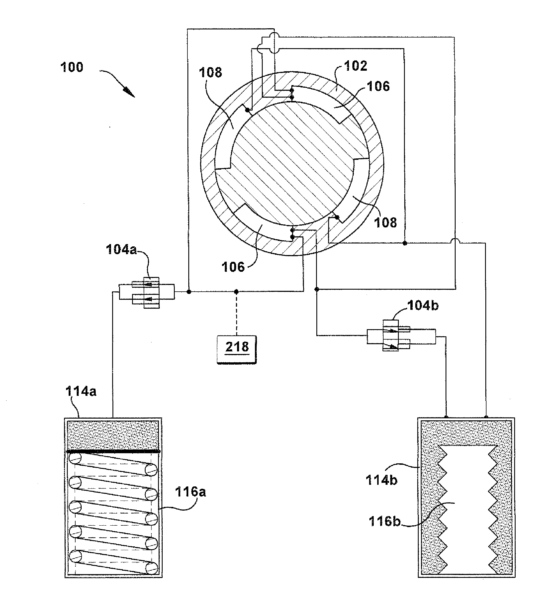
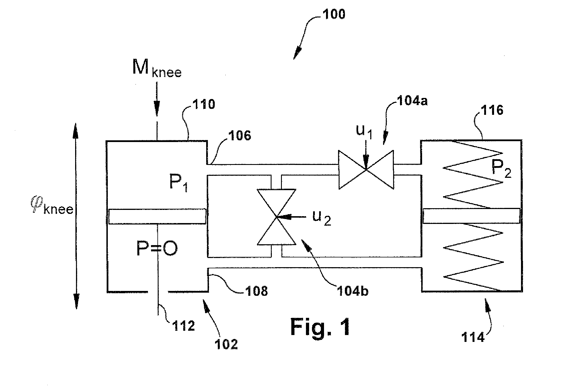
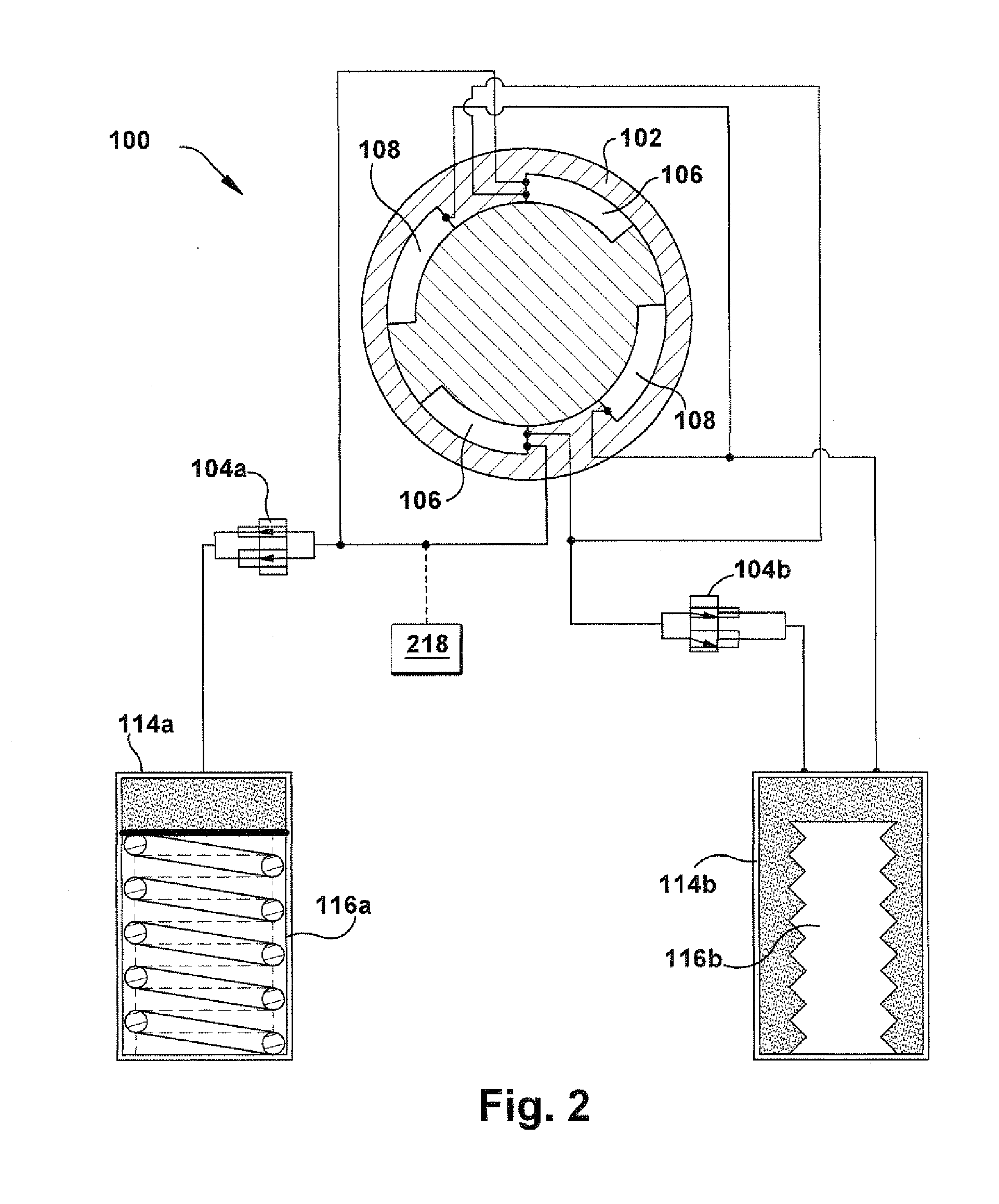
[0026]In accordance with the present invention, FIG. 1 schematically depicts a portion of an apparatus for asserting a transfemoral amputee with lower limb-involving user tasks. Here, the apparatus includes an energy-storing prosthetic knee 100, which stores energy during times of negative power in the amputee's gait cycle (characterized by a plurality of gait periods) and releases the energy as positive power to assist at a later time in the gait cycle. The operation and configuration of the prosthetic knee 100 will be described herein as being fluid-powered (e.g., hydraulic and / or pneumatic), but any suitable power scheme (e.g., electric, mechanical, spring-powered, rheological, or any other suitable type) could be used for a particular application of the present invention.

[0027]The prosthetic knee 100 includes at least one actuator 102, controlled by at least two controllable variable fluid flow resisting devices, shown and described herein as fluid valves 104a and 104b. The valv...


PUM


Abstract

An energy-storing prosthetic knee includes an upper leg structure and a lower leg structure hingedly connected to the upper leg structure. The lower and upper leg structures move pivotally relative to one another. A fluid actuator is operatively connected to the upper and lower leg structures such that relative pivotal movement of the upper and lower leg structures causes a fluid to flow in a predetermined manner within the fluid actuator. At least two controllable variable fluid flow resisting devices, an accumulator, and a control system are also provided. The control system is actuable to cause storage of the fluid energy for a predetermined length of time and release of the fluid energy at a predetermined time during the gait cycle. Both the storage and release of the fluid energy are variable by action of the control system without physical modification of other components of the prosthetic knee.

Description

RELATED APPLICATION[0001]This application claims priority from U.S. Provisional Application No. 61 / 482,445, filed 4 May 2011, the subject matter of which is incorporated herein by reference in its entirety.TECHNICAL FIELD[0002]The present invention relates to an apparatus and method for use of a prosthetic knee and, more particularly, to modeling and desired control of an energy-storing prosthetic knee.BACKGROUND OF THE INVENTION[0003]The energy cost of walking is 30-50% higher in unilateral transfemoral amputees than in able-bodied controls, and at least half of this is due to the loss of knee function. Modern commercial knees with microprocessor-controlled damping mechanisms, such as the Rheo Knee (available from Ossur Americas of Foothill Ranch, Calif.) and C-Leg (available from Otto Bock US of Minneapolis, Minn.), have only reduced the energy cost by 3-5%, compared to conventional passive prosthetic mechanisms. This suggests that an essential aspect of knee function is still mis...

Claims


Application Information

Patent Timeline
IPC IPC(8): A61F2/74
CPCA61F2002/5006A61F2002/74A61F2/68A61F2002/748A61F2/64A61F2002/701A61F2002/744A61F2002/704A61F2/70A61F2/74A61F2/744A61F2/748
Inventor SMITH, WILLIAM A.SAMOREZOV, SERGEYDAVIS, BRIAN L.VANDEN BOGERT, ANTONIE J.
Owner THE CLEVELAND CLINIC FOUND
Why Eureka
Try Eureka