Scanner with phase and pitch adjustment

a phase and pitch adjustment and scanning technology, applied in the direction of optical radiation measurement, instruments, spectrometry/spectrophotometry/monochromators, etc., can solve the problems of relatively slow measurement speed and relatively expensive manufacture of accordion fringe interferometers

Inactive Publication Date: 2013-01-17
FARO TECH INC
View PDF1 Cites 21 Cited by
  • Summary
  • Abstract
  • Description
  • Claims
  • Application Information

AI Technical Summary

Problems solved by technology

This type of accordion fringe interferometer is relatively expensive to manufacture and relatively slow in performing measurements.

Method used


Image

  • Scanner with phase and pitch adjustment
  • Scanner with phase and pitch adjustment
  • Scanner with phase and pitch adjustment

Examples


Embodiment Construction

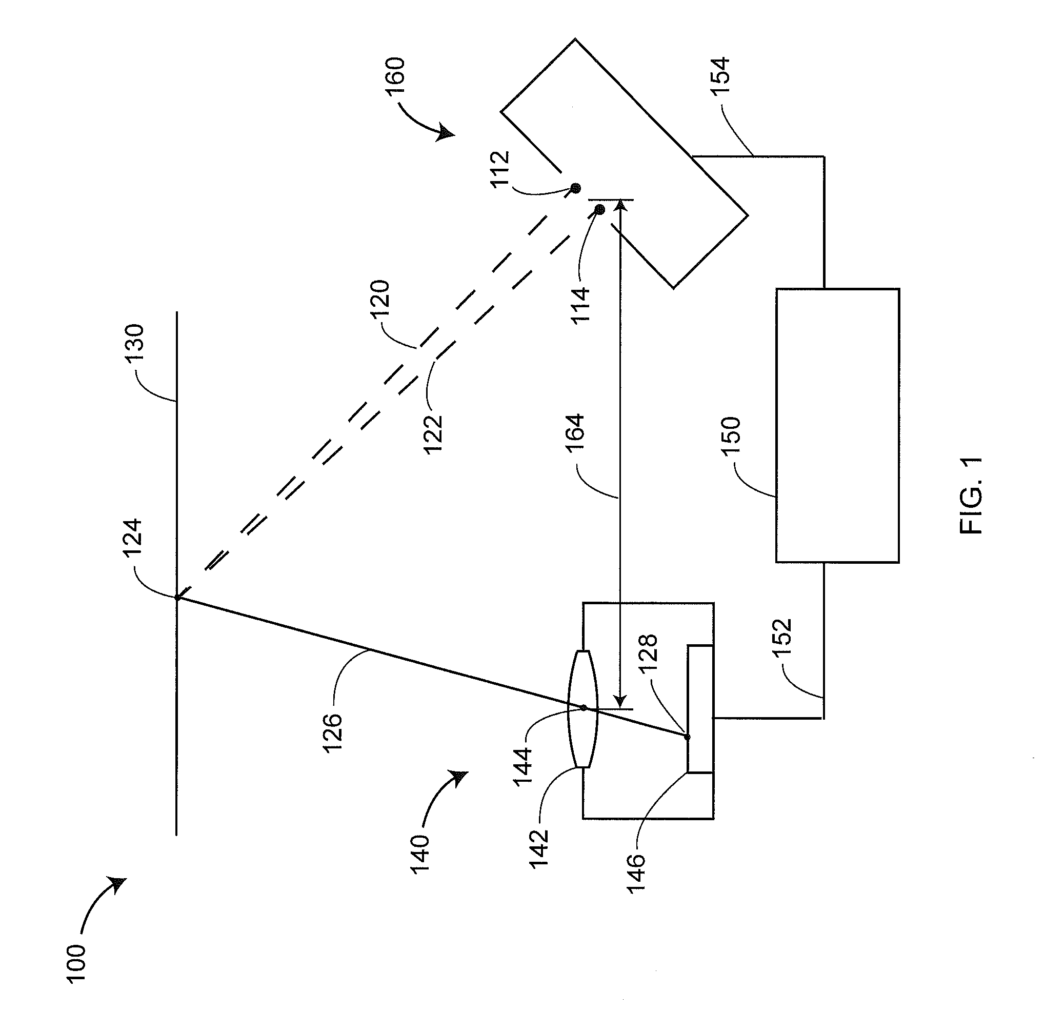
[0031]An exemplary 3D measuring device 100 that operates according to the principle of accordion fringe interferometry is shown in FIG. 1. A projector 160 under control of an electronics unit 150 produces two small spots of light 112, 114. These spots of light produce a pattern of fringes on the surface of a workpiece 130. The irradiance of the pattern at a particular point 124 is determined by the interference of the two rays of light 120, 122 at the point 124. At various points on the surface of the workpiece 130, the light rays 120, 122 interfere constructively or destructively, thereby producing the fringe pattern. A camera 140 includes a lens system 142 and a photosensitive array 146. The camera 140 forms an image on photosensitive array 146 of the pattern of light on the workpiece 130. The light from the point 124 may be considered to pass through a center of symmetry 144 of a lens system 142 to form an image point 128 on the photosensitive array. A particular pixel of the pho...


PUM


Abstract

A method for determining three-dimensional coordinates of an object point on a surface of an object, including steps of providing a transparent plate having a first region and a second region, the second region having a different wedge angle than the first region; splitting a first beam of light into a first light and a second light; sending the first light through the first region or the second region; combining the first light and the second light to produce a fringe pattern on the surface of the object, the pitch of the fringe pattern depending on the wedge angle through which the first light travels; imaging the object point onto an array point on a photosensitive array to obtain an electrical data value; determining the three-dimensional coordinates of the first object point based at least in part on the electrical data value.

Description

CROSS-REFERENCE TO RELATED APPLICATIONS[0001]The present application claims the benefit of U.S. Provisional Patent Application No. 61 / 507,763, filed on Jul. 14, 2011, the contents of which are hereby incorporated by reference in their entirety.BACKGROUND[0002]The present disclosure relates to a coordinate measuring device. One set of coordinate measurement devices belongs to a class of instruments that measure the three-dimensional (3D) coordinates of a point by projecting a pattern of light to an object and recording the pattern with a camera.[0003]A particular type of coordinate measuring device, sometimes referred to as an accordion fringe interferometer, forms the projected pattern of light by the interference of light of diverging wavefronts emitted by two small, closely spaced spots of light. The resulting fringe pattern projected onto the object is analyzed to find 3D coordinates of surface points for each separate pixel within the camera.[0004]In one implementation of an acc...

Claims


Application Information

Patent Timeline
Patent Type & Authority Applications(United States)
IPC IPC(8): G01B11/14G01B9/02
CPCG01B11/2527G01B11/2536G01B11/2531
Inventor BRIDGES, ROBERT E.KRUSE, RYANGONG, YUMCCORMACK, PAULLAFOND, EMMANUEL
Owner FARO TECH INC
Why Eureka
Try Eureka