
Part-holding fixture for grinding wedged optical flats

a technology of optical flats and parts, which is applied in the manufacture of tools, optical surface grinding machines, grinding machine components, etc., can solve the problems of operator-dependent processes and generally unrepeatability, and achieve the effect of avoiding interfering with the grinding process and saving costs

Inactive Publication Date: 2005-02-15
CORNING TROPEL
View PDF13 Cites 18 Cited by
  • Summary
  • Abstract
  • Description
  • Claims
  • Application Information

AI Technical Summary

Benefits of technology

In addition to improved repeatability, the invention is also expected to provide decreased cycle times, easier setup, less operator dependency, decreased batch sizes, and increased process flexibility.
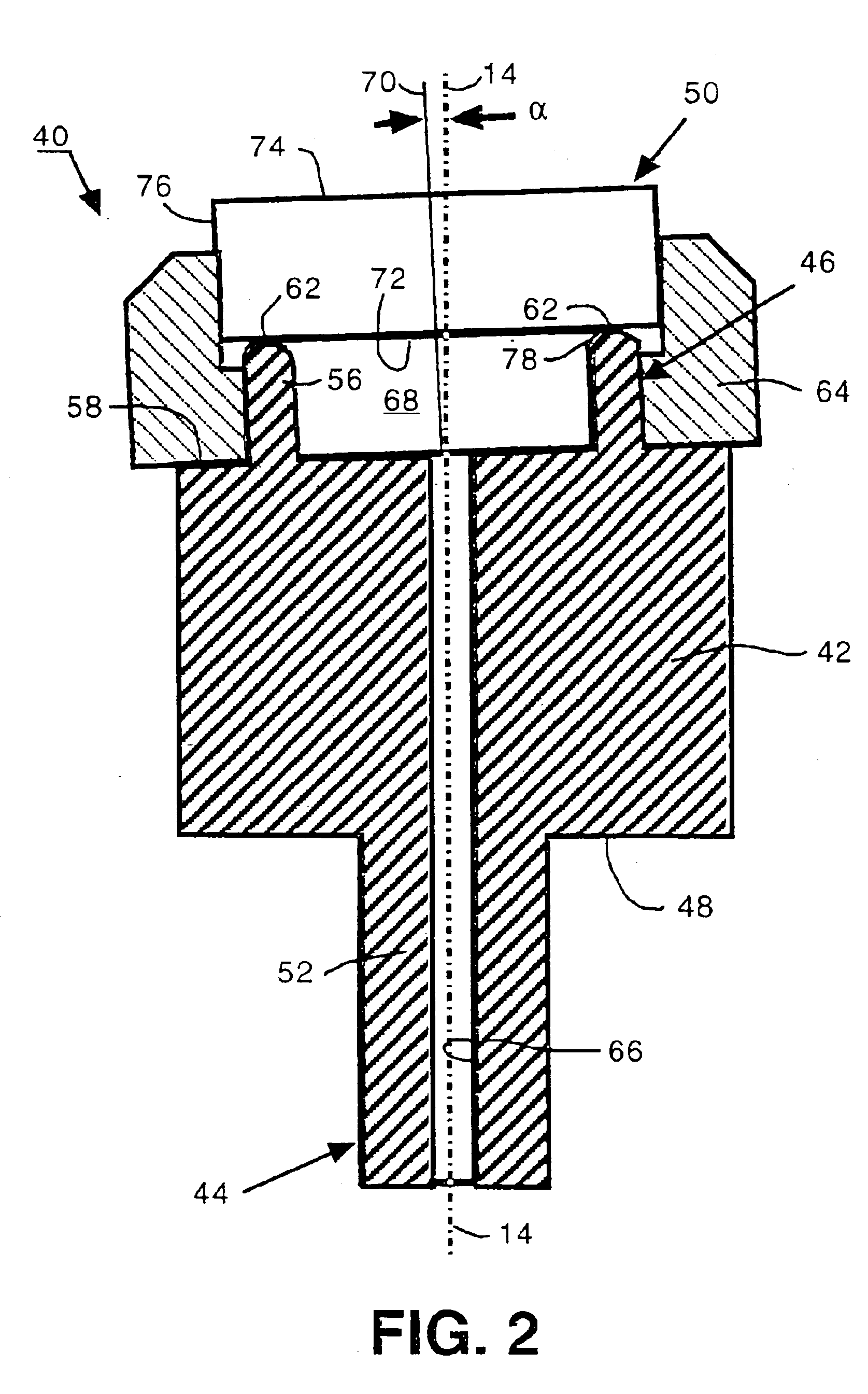
The collar is preferably shaped to engage both a periphery of the optical flat and a periphery of the fixture body. To save cost and to avoid interfering with the grinding process, the collar can be made from a soft material, such as resin. Even if the collar is struck by a fixed abrasive such as a grinding wheel, the collar is intended to have no significant effect on the grinding process.

Problems solved by technology

While single batches of optical flats can be finished to desired tolerances, the process is operator-dependent and generally unrepeatable.

Method used


Image

  • Part-holding fixture for grinding wedged optical flats
  • Part-holding fixture for grinding wedged optical flats
  • Part-holding fixture for grinding wedged optical flats

Examples


Embodiment Construction

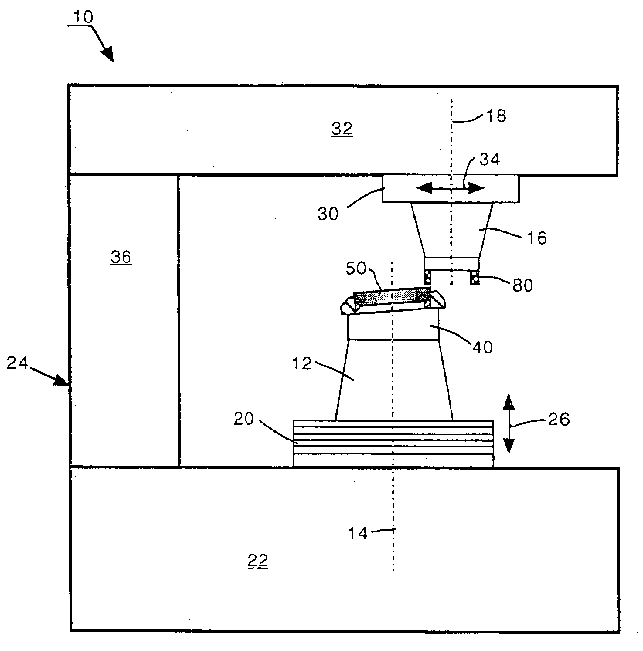
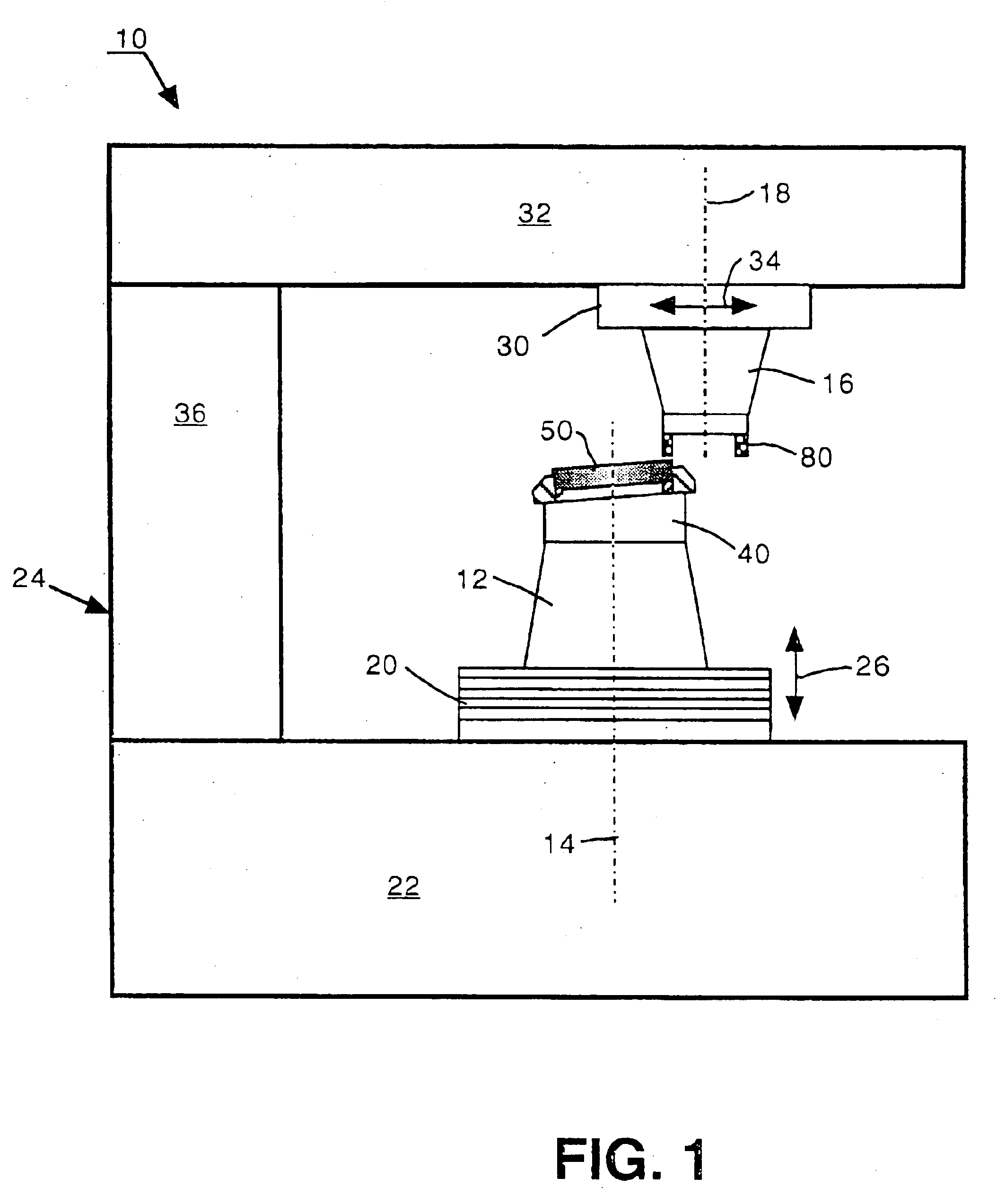
An exemplary CNC optical grinder 10 adapted for purposes of the invention is depicted in FIG. 1 as having a work spindle 12 mounted for rotation about a work spindle axis 14 and a tool spindle 16 mounted for rotation about a tool spindle axis 18. A vertical stage 20 supports the work spindle 12 above a base 22 of a machine frame 24 for translation in the vertical direction of arrows 26. A horizontal stage 30 supports, the tool spindle 16 from an arm 32 of the machine frame 24 for translation in the horizontal direction of arrows 34. A pillar 36 connects the arm 32 to the base 22 of the machine frame 24.

Although it remains preferred for the work spindle 12 to be rotatable about a work spindle axis 14 and for the tool spindle 16 to be rotatable about a tool spindle axis 18, other combinations of translational or rotational axes can be used to provide desired relative motions between the work spindle 12 and the tool spindle 16. One or more such axes is preferably used as a setup axis a...


PUM

PropertyMeasurementUnit
Pressureaaaaaaaaaa
Angleaaaaaaaaaa
Shapeaaaaaaaaaa

Abstract

A part-holding fixture is adapted for rotation about a work spindle axis and includes a mounting land that seals a back surface of an optical flat for securing the optical flat to the part-holding fixture and that inclines the back surface of the optical flat through a wedge angle for grinding wedged optical flats at repeatable wedge angles.

Description

TECHNICAL FIELDThe invention relates to the fabrication of wedged optical flats (also referred to as wedged, piano optics) and is particularly concerned with part-holding fixtures for mounting such optics on optical grinding machines.BACKGROUNDWedged optical flats, which are useful for such purposes as windows for lasers, output couplers, and beam splitters, are typically fabricated to required tolerances for finish, flatness, and wedge angle on loose-abrasive lapping machines. One or more of the optical flats are mounted between relatively rotating finishing plates in the presence of a loose abrasive. One side of the plates is weighted to fashion the desired wedge angle. While single batches of optical flats can be finished to desired tolerances, the process is operator-dependent and generally unrepeatable.SUMMARY OF INVENTIONThe invention involves a part-holding fixture for mounting wedged optical flats on fixed-abrasive grinding machines, particularly CNC (computer numeric contro...

Claims


Application Information

Patent Timeline
IPC IPC(8): B24B1/00B24B13/005B24B13/00B24B41/06
CPCB24B13/0018B24B41/067B24B13/005
Inventor ARSERIO, GREGORY J.MANNO, THOMAS E.HEATH, ROBERT E.
Owner CORNING TROPEL
Learn More