Thigh stump endoprosthesis for an exoprosthetic treatment

Inactive Publication Date: 2004-03-23
ORTHODYNAMICS GMBH
View PDF25 Cites 19 Cited by
  • Summary
  • Abstract
  • Description
  • Claims
  • Application Information

AI Technical Summary

Problems solved by technology

However, this publication gives no indication of the impl

Method used


Image

  • Thigh stump endoprosthesis for an exoprosthetic treatment
  • Thigh stump endoprosthesis for an exoprosthetic treatment

Examples


Embodiment Construction

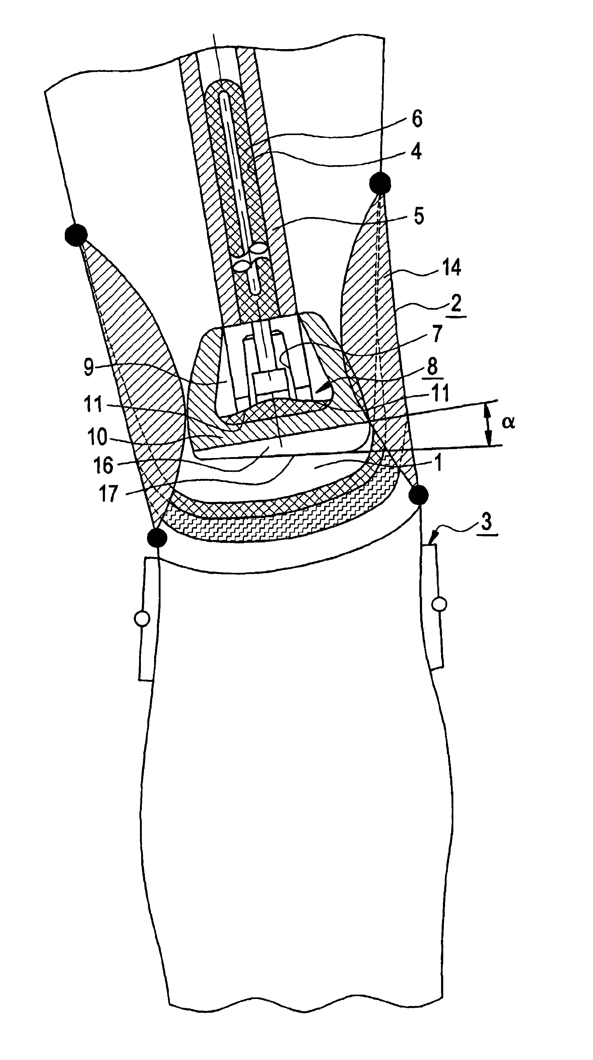
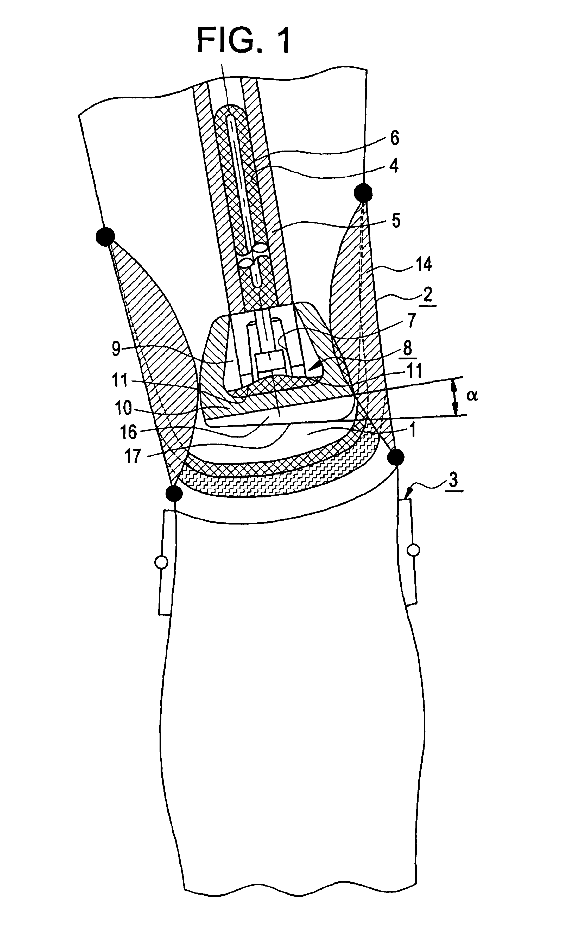
An intramedullary post 4 forms the proximal part of the post, which is set into the medullary space of the femoral stump. The surface of the post part 4 has an open-mesh, 3D spatial network structure 6, through which the bone trabeculae can grow, so that after a certain healing phase, which concerns the substrate flow, the post part 4 has become an almost integral part of the natural bone.

On the distal side, a conical adapter 7 is attached to the post part 4. This conical adapter 7 is used to attach the condyle replacement 8 to the post part 4 on the distal side.

The condyle replacement 8 is designed to simulate the shape 11 of the natural condyle of a knee joint.

The condyle replacement 8 here is coated with a shock-absorbing layer 10 of silicon.

The support 16 is connected to the condyle replacement 8 and to the covering, shock-absorbing layer. The support 16 is designed to be wedge-shaped and has a wedge angle to the horizontal ranging from 5.degree.<.alpha.<9.degree..

The support 16...


PUM


Abstract

The invention relates to a thigh stump endoprosthesis for an exoprosthetic treatment of a patient whose leg has been amputated in the thigh area, whereby the thigh stump can be pulled into a shaft to which the replica of a lower leg part and foot part of the prosthesis is attached. The inventive prosthesis includes a proximal shaft part which can be inserted inside a femur stump, whereby the shaft part is at least partially covered by an open-mesh three-dimensional spatial network structure, and includes a conical adapter on the distal end thereof. A condyle replacement which re-creates the shape of natural condyles of a knee joint can be coupled to the shaft part by means of said adapter. A cuneiform support can be joined to the condyle replacement with a wedge angle alpha which restores the valgity of the leg.

Description

This invention concerns a femoral stump endoprosthesis for exoprosthetic care of a patient whose leg has been amputated in the femoral region. The femoral stump can be drawn into a shaft to which the simulation of a knee, lower leg and foot part of the prosthesis is connected. The endoprosthesis has a proximal post part, which can be set in a femoral stump, whereby the post part is covered, at least partly, with an open-mesh, 3D spatial network structure and has a conical adapter on its distal end, by means of which a condyle replacement, which simulates the shape of the natural condyle of a knee joint, is attached to the post part.DESCRIPTION OF THE RELATED ARTAn implant is known (U.S. Pat. No. 5,766,251) from the field of surgery that is designed as a wedge-shaped equalizer that permits corrections in the angle of valgity, for example. The wedge-shaped implant is used, inter alia, in the joint area of the tibia, whereby the tibia plateau is lifted on one side according to the angl...

Claims


Application Information

Patent Timeline
IPC IPC(8): A61F2/28A61F2/80A61F2/50A61B17/72A61B17/68A61F2/30A61F2/00A61F2/38A61F2/60A61F2/64A61F2/62
CPCA61F2/2814A61F2/80A61B17/72A61F2/30749A61F2/30942A61F2/3859A61F2/64A61F2002/2825A61F2002/3007A61F2002/3021A61F2002/3023A61F2002/30332A61F2002/30476A61F2002/30563A61F2002/30878A61F2002/30909A61F2002/3092A61F2002/5038A61F2002/607A61F2002/7887A61F2220/0025A61F2220/0033A61F2230/0067A61F2230/0069
Inventor GRUNDEI, HANS
Owner ORTHODYNAMICS GMBH
Why Eureka
Try Eureka