Diode laser array coupling optic and system

a technology of diode laser array and coupling optic, which is applied in the field of diode lasers, can solve the problems of reducing the beam quality in the fast axis, affecting the efficiency of the fast axis, and the poor beam quality or brightness of high-power diode laser arrays, so as to reduce the divergence of the emitters, reduce the beam steering, and effectively coupled

Inactive Publication Date: 2008-10-28
NLIGHT INC
View PDF17 Cites 19 Cited by
  • Summary
  • Abstract
  • Description
  • Claims
  • Application Information

AI Technical Summary

Benefits of technology

[0007]The present invention provides an optic for use in coupling the output of a diode laser array into an optical fiber array. The coupling optic has a planar back surface which, during use with a diode laser array, is positioned substantially parallel to the front face of the laser array. In one aspect of the invention, the coupling optic is fabricated from a single substrate and is comprised of a plurality of optical elements. The center to center spacing of the optical elements matches that of both the emitters of the diode laser array and the individual fibers of the optical fiber array. The front surface of each optical element is tilted, thus preventing reflected laser radiation from resonating within the diode laser's emitters. Preferably the wedge angle for the tilted front surface is greater than 2 mrad, thus accomplishing the goal of limiting feedback into the emitters, and less than 4 mrad, thus reducing beam steering. Additionally each optical element is shaped to reduce the divergence of the emitters in the fast axis, thus allowing the output from each emitter to be effectively coupled into the corresponding optical fiber.
[0009]In at least one embodiment of the invention, AR coatings are applied to the surfaces of the optical elements of the coupling optic that are adjacent to the output facets of the diode laser array and the input surfaces of the optical fibers, thereby further reducing reflections and scattered light from entering into the emitters.

Problems solved by technology

The beam quality, or brightness, of high power diode laser arrays is generally very poor, and thus inadequate for many applications.
While this approach improves the beam quality in the slow axis, it reduces the beam quality in the fast axis.
Unfortunately alignment of the AR coated surfaces as well as properly positioning the cylindrical lens is a time consuming process.

Method used


Image

  • Diode laser array coupling optic and system
  • Diode laser array coupling optic and system
  • Diode laser array coupling optic and system

Examples


Embodiment Construction

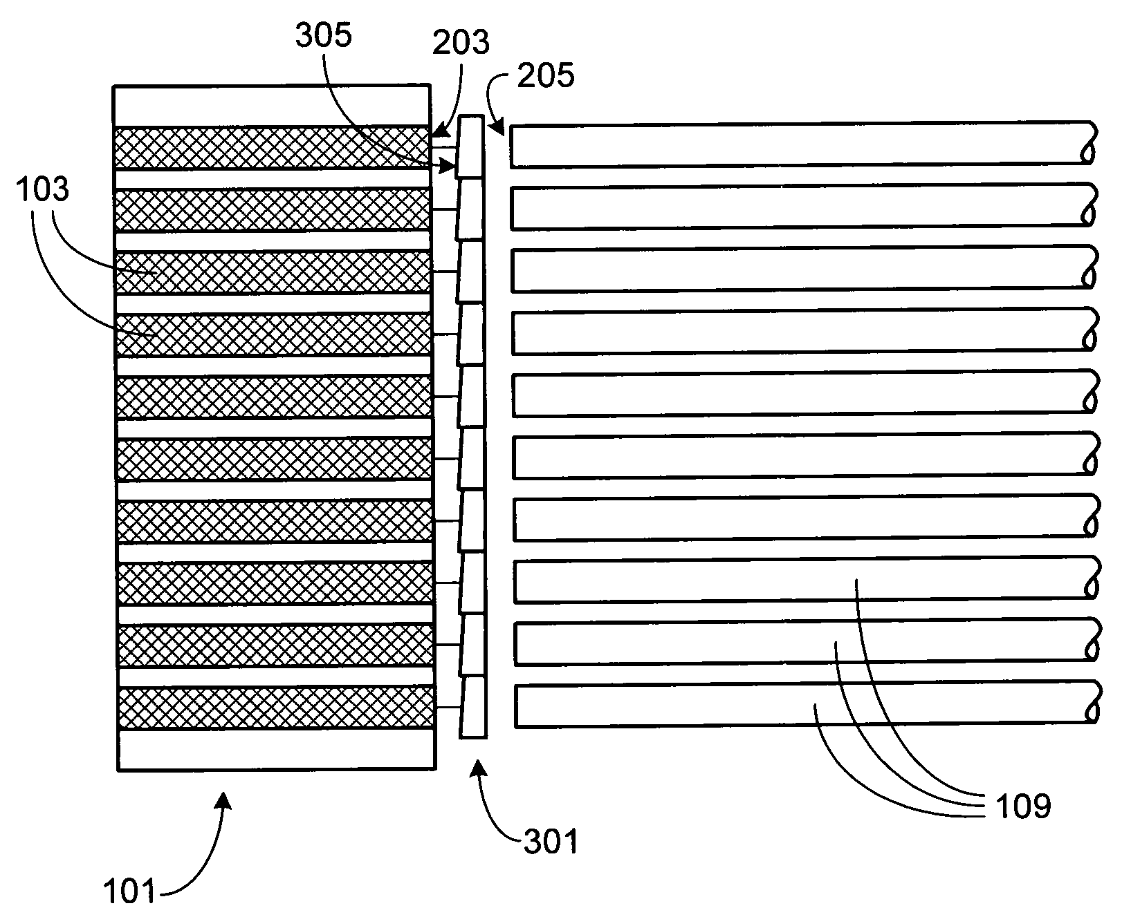
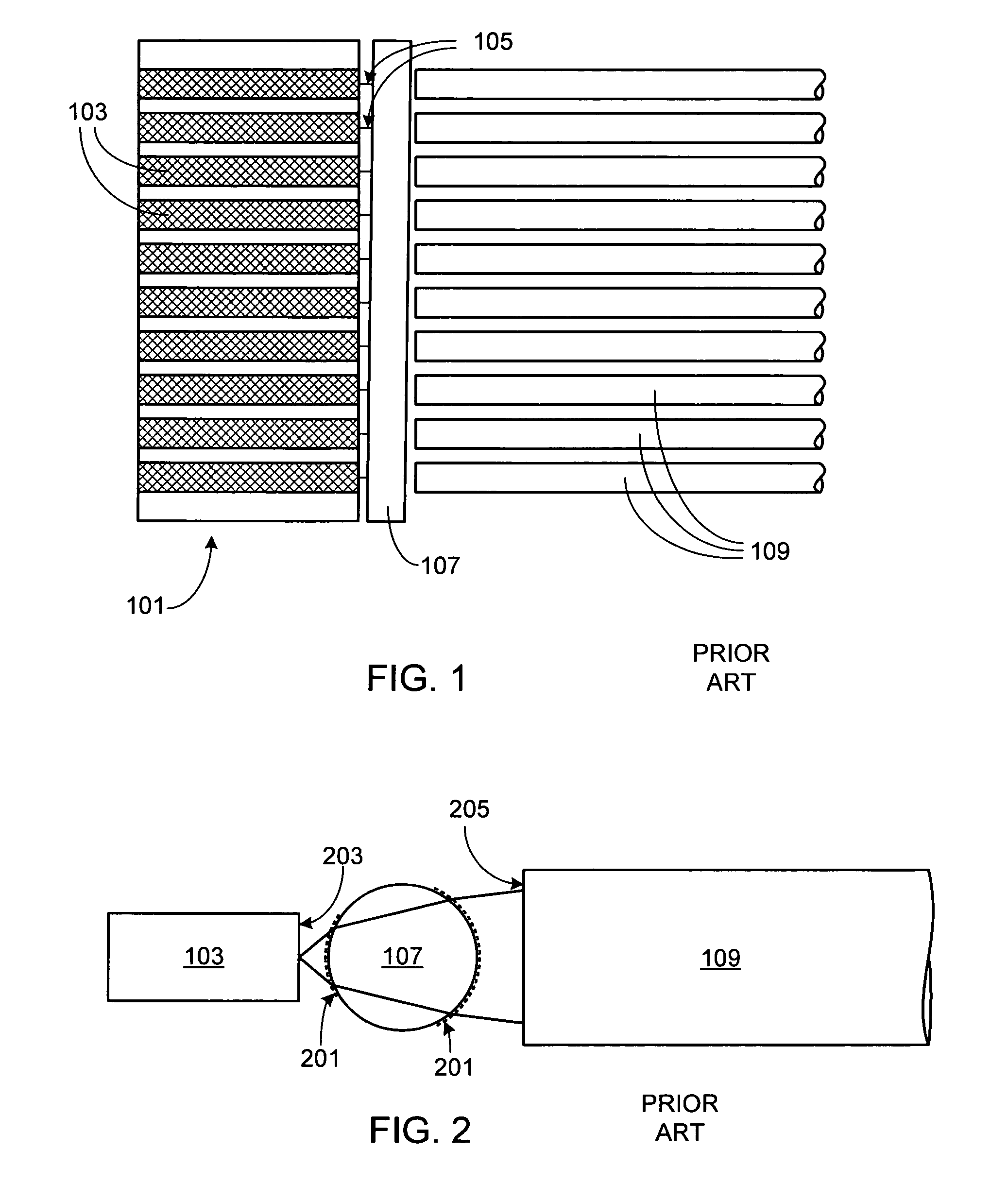
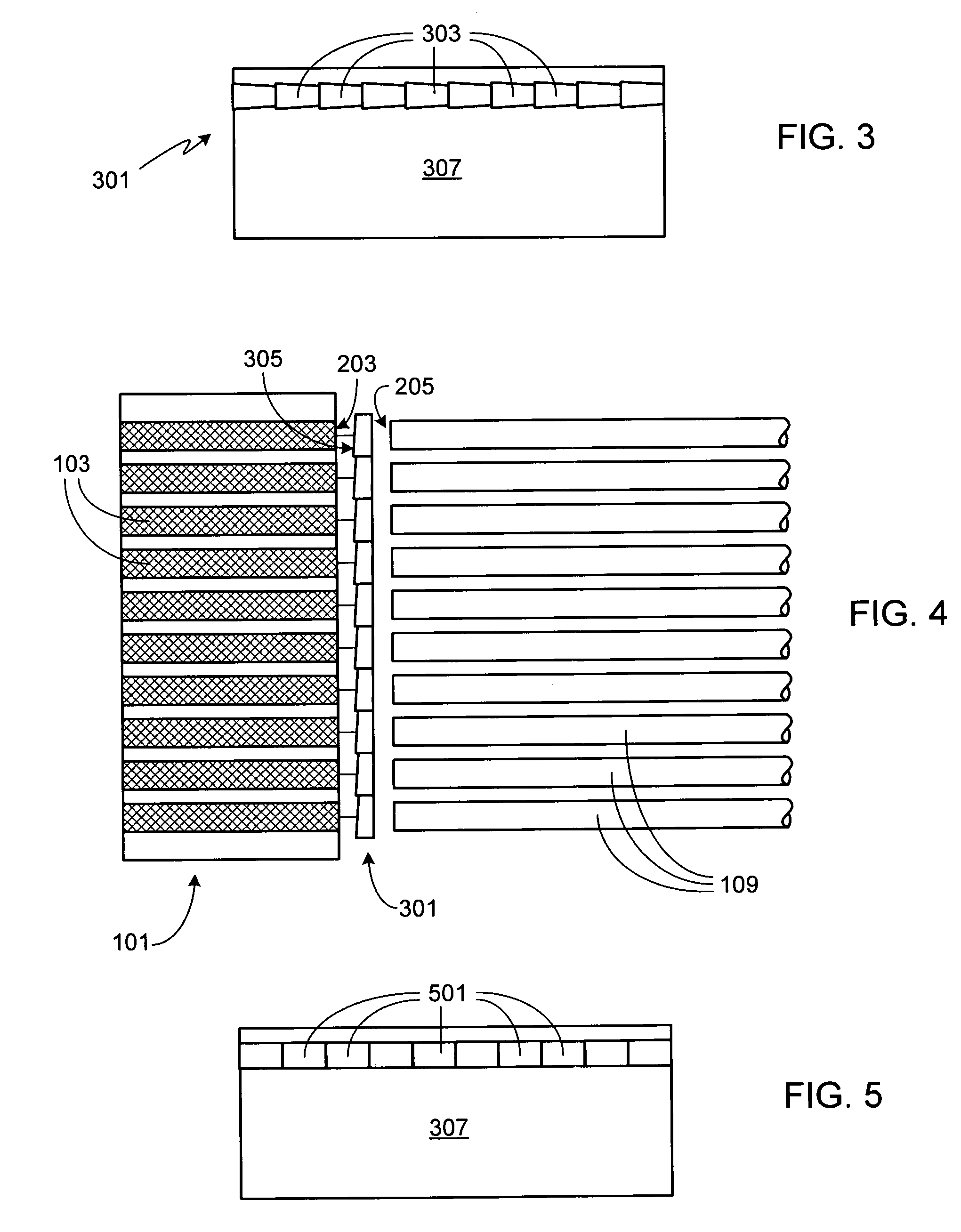
[0022]FIG. 1 is an illustration of a diode laser array 101 (e.g., a diode laser bar or stack) consisting of a plurality of emitters 103, each emitting a beam of radiation 105. In accordance with the prior art, a cylindrical lens 107 is positioned between array 101 and a plurality of optical fibers 109. Cylindrical lens 107 compensates for the high angular divergence in the direction perpendicular to the diode junction of the emitters, typically reducing the beam divergence in the fast axis to less than that of the slow axis, thereby easing the assembly tolerances of the overall system compared to an assembly which does not use any coupling optics (i.e., one in which each fiber is simply placed in close proximity to the emitter to which it is to be coupled).

[0023]In a typical diode laser array 101, emitters 103 will have multiple spatial modes. As a result, optical fibers 109 are preferably multi-mode as well. Since the optical fibers are multi-mode, coupling lens 107 does not have t...


PUM


Abstract

A single piece optic for coupling the output of a diode laser array into an optical fiber array is provided. The coupling optic has a planar back surface which, during use with a diode laser array, is positioned substantially parallel to the front face of the laser array. The coupling optic is fabricated from a single substrate and is comprised of a plurality of optical elements. Depending upon the technique used to fabricate the optical elements, the individual optical elements may be trapezoidally-shaped or rectangularly-shaped. The front surface of each optical element is tilted, thus preventing reflected laser radiation from resonating within the diode laser's emitters. Preferably the wedge angle for the tilted front surface is greater than 2 mrad, thus accomplishing the goal of limiting feedback into the emitters, and less than 4 mrad, thus reducing beam steering. Additionally each optical element is shaped to reduce the divergence of the emitters in the fast axis, thus allowing the output from each emitter to be effectively coupled into the corresponding optical fiber.

Description

FIELD OF THE INVENTION[0001]The present invention relates generally to diode lasers and, more particularly, to a method and apparatus for coupling the output of a diode laser array to a fiber array.BACKGROUND OF THE INVENTION[0002]The beam quality, or brightness, of high power diode laser arrays is generally very poor, and thus inadequate for many applications. A simple approach to improving the output from such an array is to couple each element of the array into a corresponding fiber in a linear fiber array. The output end of the fiber array can be arranged, as desired, for example into a circular bundle. While this approach improves the beam quality in the slow axis, it reduces the beam quality in the fast axis. Further improvement in beam quality can be achieved by interposing coupling optics between the diode laser array and the fiber array.[0003]U.S. Pat. No. 5,127,068 discloses using a small diameter multimode optical fiber as the coupling optics between a diode laser and a b...

Claims


Application Information

Patent Timeline
Patent Type & Authority Patents(United States)
IPC IPC(8): G02B6/32G02B6/04H01S5/00
CPCG02B6/4206G02B6/4249H01S5/4025
Inventor KARLSEN, SCOTT R.
Owner NLIGHT INC
Why Eureka
Try Eureka