Metamaterial for separating electromagnetic wave beam

Active Publication Date: 2013-01-17
KUANG CHI INST OF ADVANCED TECH +1
View PDF1 Cites 2 Cited by
  • Summary
  • Abstract
  • Description
  • Claims
  • Application Information

AI Technical Summary

Benefits of technology

The present patent is about a special material that can separate and control the direction of electromagnetic waves. This material can be used to create things like lenses or filters for controlling the movement of light. The invention is useful for creating large-area devices that can manage large amounts of electromagnetic waves.

Problems solved by technology

Because these crystals are mostly naturally occurring materials and their response characteristics to electromagnetic wave beams are invariable, it is impossible to flexibly control exiting angles of the separated electromagnetic waves.
Consequently, these crystals cannot be widely used flexibly.
Moreover, the natural crystals have limited sizes and also it is difficult to produce a man-made crystal with a large size; and if a number of crystals produced are spliced or bonded together to produce a larger crystal, then refraction and reflection caused by the joining or bonding surface would adversely affect the effect of separating the electromagnetic wave beam.

Method used


Image

  • Metamaterial for separating electromagnetic wave beam
  • Metamaterial for separating electromagnetic wave beam
  • Metamaterial for separating electromagnetic wave beam

Examples


first embodiment

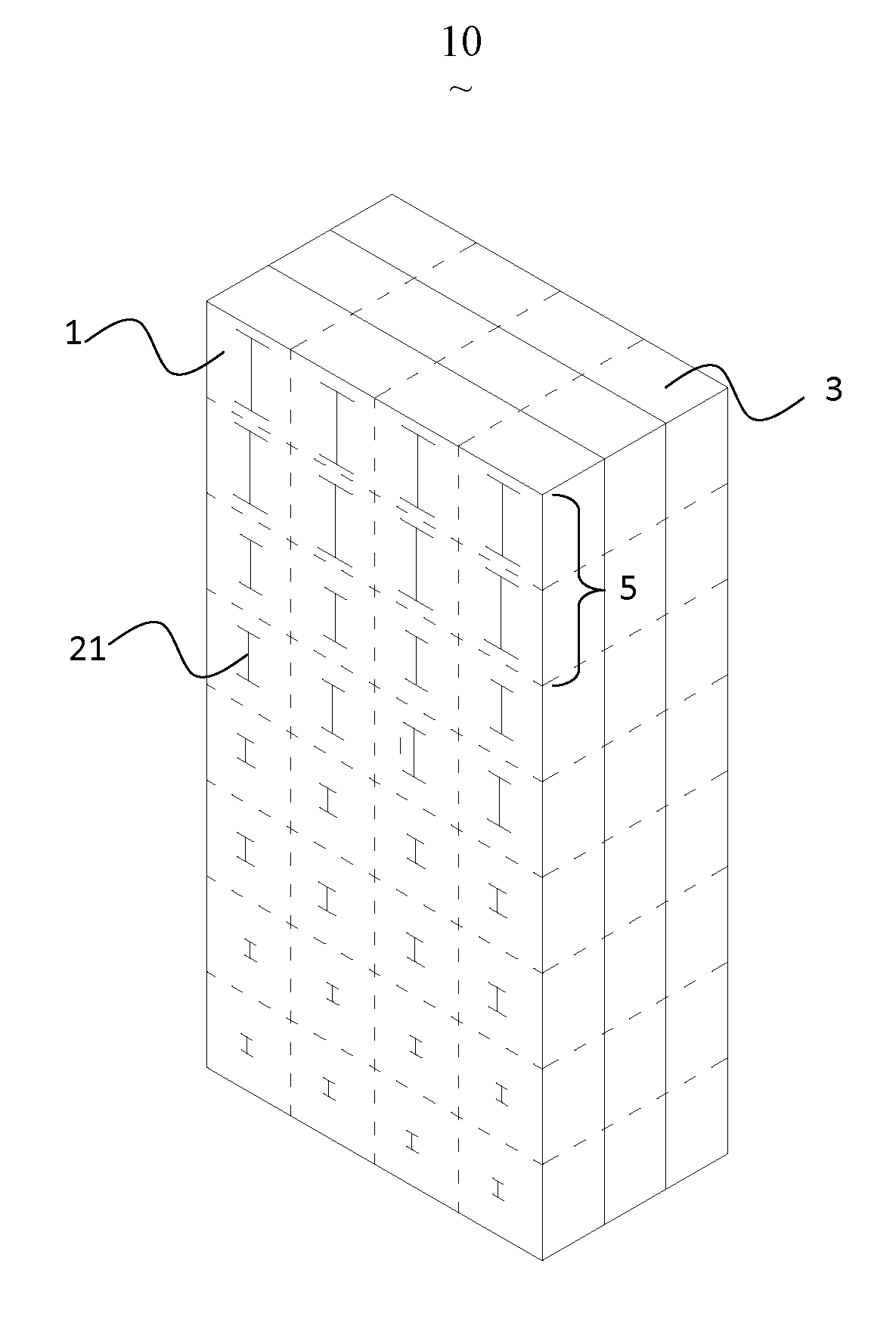
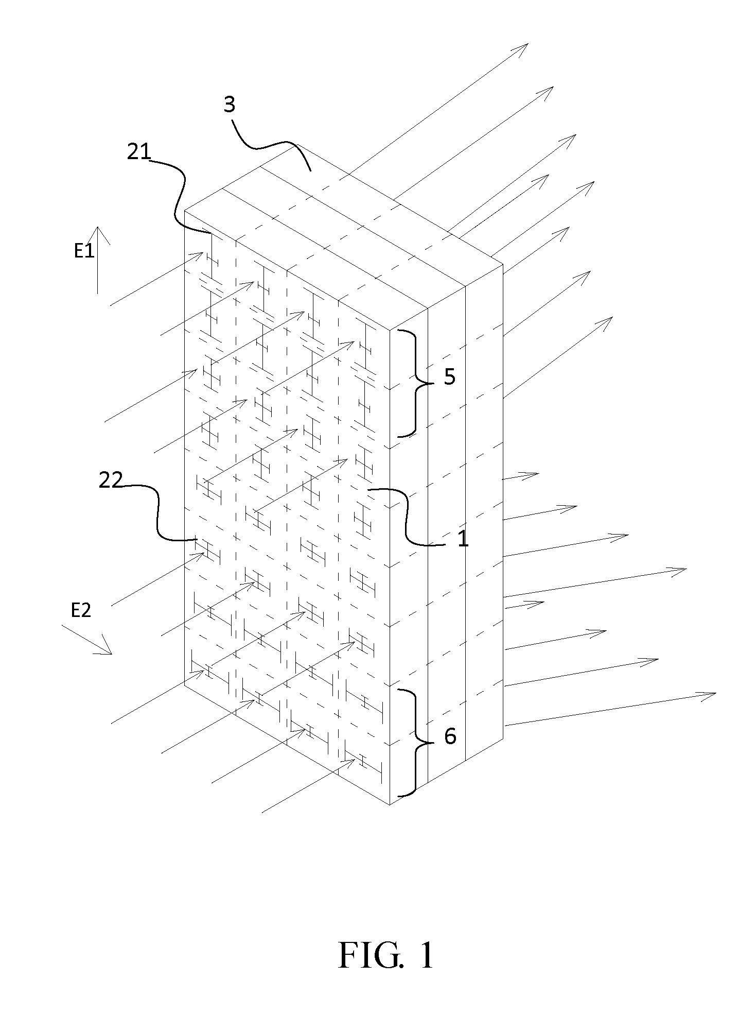
[0027]A metamaterial 10 for separating an electromagnetic wave beam according to the present disclosure is adapted to separate two incident electromagnetic waves whose electric fields are orthogonal to each other. Referring to FIG. 1, there is shown a schematic view of the metamaterial 10. The metamaterial 10 comprises at least one metamaterial sheet layer 3. The metamaterial sheet layers 3 are arranged and assembled together equidistantly, or are stacked together with a front surface of one sheet layer 3 making direct contact with a back surface of an adjacent sheet layer 3. Each of the sheet layers 3 further comprises a sheet-like substrate 1 of which a front surface and a back surface are parallel to each other, and first man-made microstructures 21 and second man-made microstructures 22 disposed in an array form respectively on the substrate 1.

[0028]The first man-made microstructures 21 and the second man-made microstructures 22 are each of a 2D or 3D structure consisting of at ...

second embodiment

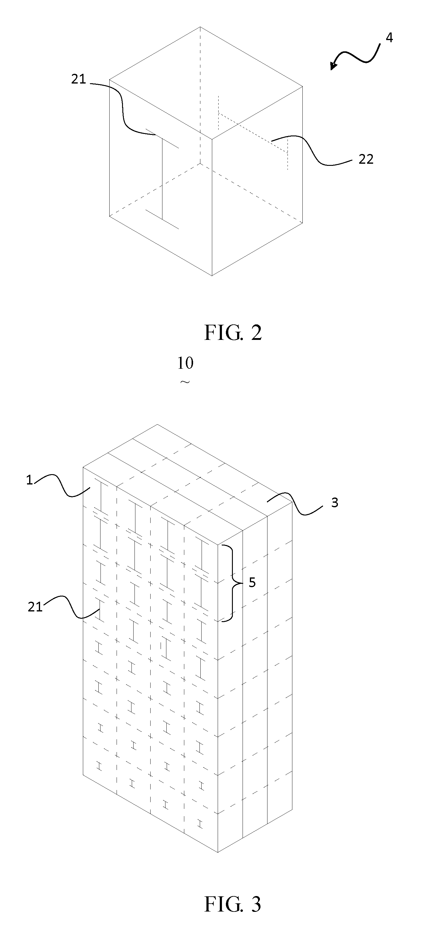
[0035]FIG. 3 is a schematic structural view of the metamaterial 10 according to the present disclosure. In this embodiment, the metamaterial 10 is formed of a plurality of metamaterial unit cells 4 arranged in an array form. FIG. 2 is a schematic view of an embodiment of a metamaterial unit cell 4 of the metamaterial 10. In this embodiment, the first man-made microstructures 21 and the second man-made microstructures 22 are arranged in an array form on two opposite side surfaces of the substrate 1 respectively. The embodiment shown in FIG. 3 differs from the embodiment shown in FIG. 1 in that, the first man-made microstructures 21 and the second man-made microstructures 22 are arranged on opposite side surfaces respectively, but not on a same surface as in the embodiment shown in FIG. 1; and other aspects including distributions of the first man-made microstructures 21 and the second man-made microstructures 22 are all the same as the embodiment shown in FIG. 1. FIG. 4 and FIG. 5 ar...


PUM


Abstract

A metamaterial for separating an electromagnetic wave beam is disclosed. Two kinds of man-made microstructures are attached on a substrate of the metamaterial. The first man-made microstructures each have a principal optical axis parallel to a first electric field direction, and the second man-made microstructures each have a principal optical axis parallel to a second electric field direction. The metamaterial comprises a first region and a second region. The first man-made microstructures in the first region have the largest geometric size and the first man-made microstructures in other regions increase in geometric size continuously in a direction towards the first region; and the second man-made microstructures in the second region have the largest geometric size and the second man-made microstructures in other regions increase in geometric size continuously in a direction towards the second region.

Description

FIELD OF THE INVENTION[0001]The present disclosure generally relates to the technical field of metamaterials, and more particularly, to a metamaterial for separating an electromagnetic wave beam.BACKGROUND OF THE INVENTION[0002]A metamaterial is formed of a substrate made of a non-metal material and a plurality of man-made microstructures attached on a surface of the substrate or embedded inside the substrate. Each of the man-made microstructures is of a two-dimensional (2D) or three-dimensional (3D) structure consisting of at least one metal wire. Each of the man-made microstructures and a substrate portion to which it is attached form one metamaterial unit cell. Correspondingly, just like a crystal which is formed of numerous crystal lattices arranged in a certain manner, the whole metamaterial consists of hundreds of or thousands of or millions of or even hundreds of millions of such metamaterial unit cells, with each of the lattices corresponding to a metamaterial unit cell form...

Claims


Application Information

Patent Timeline
IPC IPC(8): G02B27/10
CPCH01Q15/0086H01Q15/0033H01Q15/02
Inventor LIU, RUOPENGXU, GUANXIONGZHANG, YANGYANG
Owner KUANG CHI INST OF ADVANCED TECH
Why Eureka
Try Eureka