Motion vector detection device, method for controlling the same, and image capturing apparatus

Active Publication Date: 2017-06-01
CANON KK
View PDF2 Cites 4 Cited by
  • Summary
  • Abstract
  • Description
  • Claims
  • Application Information

AI Technical Summary

Benefits of technology

[0009]The present invention was made in order to solve at least one of the problems of such conventional techniques, and provides a motion vector de

Problems solved by technology

However, the above-described Patent Documents do not take into consideration controlling a motion vector detection method based on a factor other than the object and imaging lens state.
Furthermore, the targets in the motion vector detection method that are subject to control are limited to the positions and the numbers of representative points and template blocks and the shape and the size of se

Method used


Image

  • Motion vector detection device, method for controlling the same, and image capturing apparatus
  • Motion vector detection device, method for controlling the same, and image capturing apparatus
  • Motion vector detection device, method for controlling the same, and image capturing apparatus

Examples


first embodiment

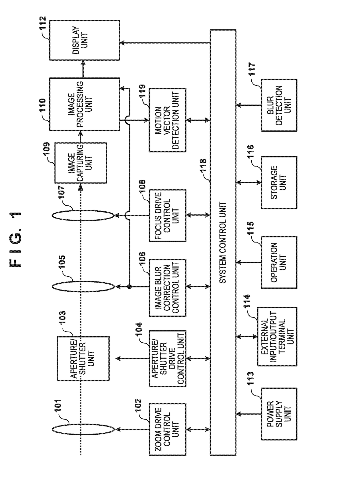
[0022]FIG. 1 is a block diagram illustrating an example of a functional configuration of a digital camera according to the present embodiment. A zoom unit 101, an aperture / shutter unit 103, an image blur correction unit 105, and a focus unit 107 constitute an imaging optical system. The imaging optical system may be of an exchangeable lens type or a non-detachable type.

[0023]The zoom unit 101 includes a lens for changing a field angle (focal length) of the imaging optical system, and is driven by a zoom drive control unit 102. The aperture / shutter unit 103 includes an aperture having a mechanical shutter function, and is driven by an aperture / shutter drive control unit 104. The image blur correction unit 105 (referred to also as “correction unit”) includes a shift lens, and is driven by an image blur correction control unit 106. Note that the present embodiment performs optical image-blur correction in which the shift lens is driven, but an imaging element may be driven. Furthermore...

second embodiment

[0081]Hereinafter, a second embodiment according to the present invention will be described. In the first embodiment, motion vector detection processing is controlled by changing settings based on a use of a motion vector. In the present embodiment, motion vector detection processing is controlled by changing settings based on the detection of specific movement, specifically, large movement in a specific direction, of an apparatus provided with the motion vector detection device.

[0082]In the present embodiment, it is assumed that the apparatus provided with the motion vector detection device is the digital camera 100 described in the first embodiment, and descriptions of the configurations of the digital camera 100 are omitted. Furthermore, the following will describe a configuration for changing a setting in accordance with detection of a panning operation, which serves as an example of the large movement in a specific direction of the apparatus provided with the motion vector dete...

third embodiment

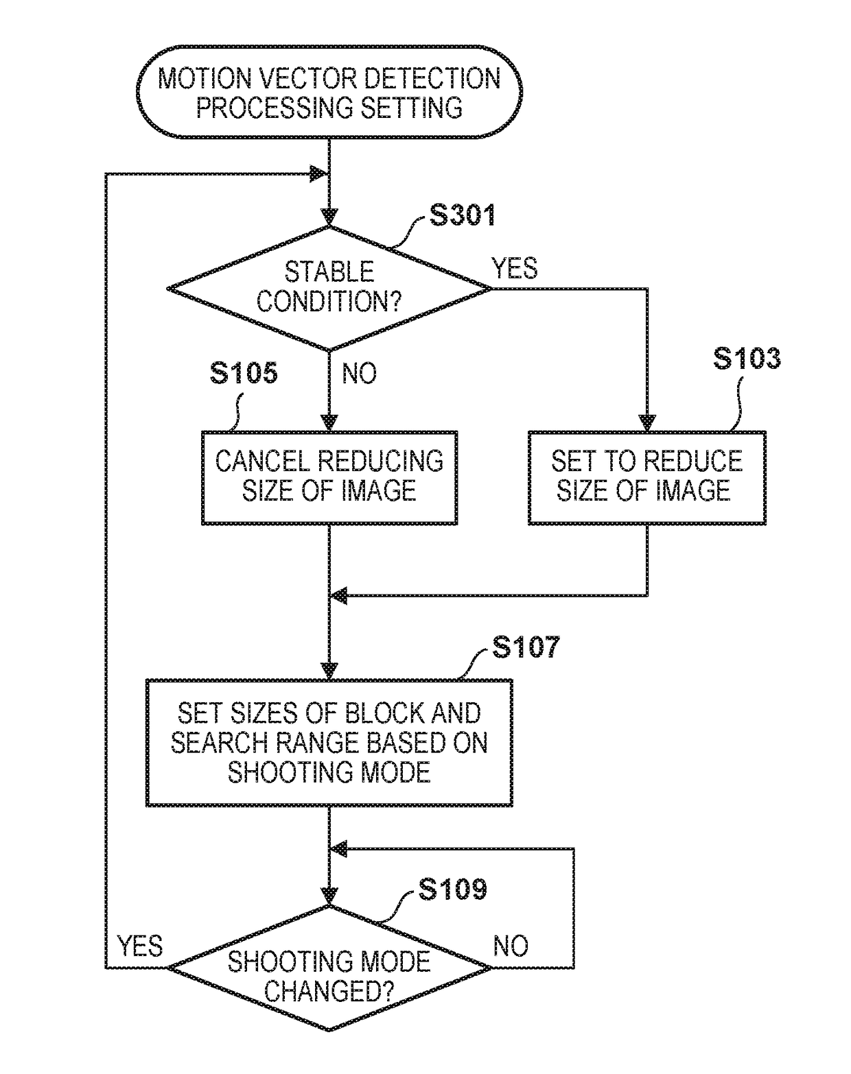
[0093]Hereinafter, a third embodiment of the present invention will be described. In the present embodiment, motion vector detection processing is controlled by changing settings based on the detection of specific movement using an apparatus provided with the motion vector detection device, specifically, sufficiently small movement. In the present embodiment, it is assumed that the apparatus provided with the motion vector detection device is the digital camera 100 described in the first embodiment, and descriptions of configurations of the digital camera 100 are omitted.

[0094]FIG. 7 is a flowchart illustrating an overview of an operation for setting motion vector detection processing according to the present embodiment. In FIG. 7, the same reference numerals as those of FIG. 4 are given to common processing with the first embodiment.

[0095]In step S301, the system control unit 118 determines whether or not the digital camera 100 is in a stable condition, based on the amount of blur ...


PUM


Abstract

A setting regarding detection of a motion vector between a plurality of images is set (changed) based on at least one of a use of the motion vector, and movement of an apparatus provided with a motion vector detection device. The setting regarding detection of a motion vector includes at least one of a setting regarding the plurality of images, and a setting regarding an image area for use in detection. The motion vector detection device that can flexibly control a motion vector detection method is provided.

Description

BACKGROUND OF THE INVENTION[0001]Field of the Invention[0002]The present invention relates to a motion vector detection device, a method for controlling the same, and an image capturing apparatus.[0003]Description of the Related Art[0004]A technique for detecting a motion vector between two frame images, and correcting an image blur based on the motion vector is known. For example, template matching is known as a method for detecting a motion vector between frame images.[0005]When template matching is used to detect a motion vector, one of the two frame images is referred to as an original image, and the other one is referred to as a reference image. In the original image, a rectangular region of a predetermined size is set as a template block, and in the reference image, a rectangular region for use in calculating a correlation value is set as a search range. Then, correlation of the template block with the reference image is calculated for various positions in the search range, an...

Claims


Application Information

Patent Timeline
IPC IPC(8): H04N5/232G06T7/20G06T3/40
CPCH04N5/23216G06T3/40H04N5/23264G06T7/2013H04N5/23254H04N23/682H04N23/6811G06T2207/20012G06T2207/20021G06T7/223G06T7/248H04N23/667
Inventor IKEDA, SHUNICHIRO
Owner CANON KK
Why Eureka
Try Eureka